NOTE
3 Aug 2019: Renamed "Measurement of Concrete Works" and incorporated HKSMM4 Revised 2018.
25 Dec 2014: Created under the name of "Standard Method of Quantifiable Modelling" intended to deal with BIM.
INTRO
-
"HKSMM4" means Hong Kong Standard Method of Measurement of Building Works - Fourth Edition, 2005.
- "HKSMM4R" means Hong Kong Standard Method of Measurement of Building Works - Fourth Edition Revised 2018.
- "SMM" means HKSMM4 or HKSMM4R as the case may be.
- Item descriptions are listed here in elemental order showing levelled classification and required properties, preceded by some definitions and measurement rules, and followed by some supplementary rules in brackets.
- Sub-levels are indented, and are subject to higher level descriptions above them.
- Elements are shown in bold capitals. Work items are shown in bold.
- ";" is used to separate different properties which should be stated for a work item.
- Descriptions separated by “|” within a property are alternatives, with the default given first and deemed to apply if not otherwise stated, but properties specified as “stated” are mandatory. “|” if given in a new line is for clearer presentation only.
- "#" denotes deviations from SMM.
- "Cube", "Sup", "Run" and "Nr" respectively mean m3, m2, m and number.
GENERALLY
- Rules
- Unless otherwise stated, measure all work net as fixed in its place.
- Deduct concrete from void > 0.05 m3 or opening > 0.10 m2.
- Deduct formwork from opening > 1.00 m2.
- Do not deduct formwork to structural walls, columns and beams intersected by end of abutting beams.
- HKSMM4 - Measure Super for formwork > 300 mm wide, otherwise measure Run (unless narrow width caused by openings), in width stages of 100 mm, i.e. 0 – 100 mm | 100 – 200 mm | 200 – 300 mm.
- HKSMM4R - Measure Super for formwork > 300 mm wide, otherwise measure Run.
- Measurement Approach
- Measure all concrete and formwork floor by floor between consecutive floor levels.
- Group vertical rreinforcement bars passing through different floors into the main floor passed.
- Measure overall first and make adjustments later.
- Deal with the effects on various elements at the same time when adjusting for the junctions of walls, columns, beams and slabs because the dimensions at the junctions are common and can be shared.
- Measure as one composite item, sum up the total quantity, then generate component items and quantities from the total quantity, e.g. length first, generating secondary quantities of area and volume.
- Coding
- Code to give suffiicient and self-explanatory information to represent different properties (parameters) of a composite item so that related secondary quantities can be generated from it.
- Use code segments to represent different properties and values.
- Code segments can be skipped for default properties.
MEASUREMENT OF CONCRETE WALLS
- Legend
![]()
![]()
- SMM Rules
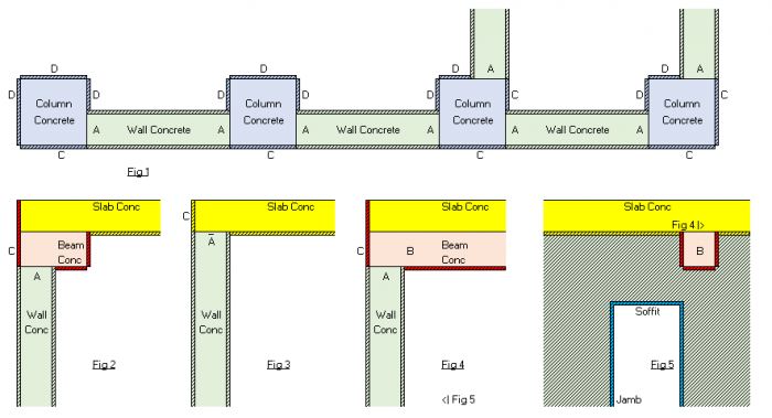
- HKSMM4 and HKSMM4R Section VII (a) M.16 says, "Concrete walls are measured between columns or projections and up to the soffits of beams and slabs."
- HKSMM4 and HKSMM4R Section VII (a) M.12 says, "The measurement of suspended slabs is taken across columns and beams, except where the columns or beams are of a different mix." It does not mention walls.
- HKSMM4 and HKSMM4R Section VII (d) M.1 says, "Except where otherwise stated, formwork is measured to concrete surfaces of the finished structure which require support during casting."
- Wall concrete and formwork should therefore be measured as shown in Fig 1 to Fig 5 below.
- Formwork at junctions of walls with columns, beams and slabs (A below) is DEDUCTED because there is no formwork there.
- Wall concrete and formwork at junctions with beams crossing over the walls (B below) are DEDUCTED because there is no exemption rule.
- Customary Deviations from SMM Rules for structural walls
- Reasons for deviations
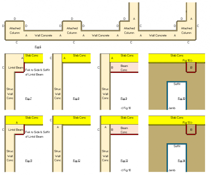
- In the case of structural walls, the beam in Fig 2 becomes a lintol beam, the beam in Fig 4 abuts the wall instead of crossing over the wall, and the columns become attached columns.
- Concrete in structural walls, attached columns and lintol beams are usually cast at the same time after the erection of the formwork as a whole.
- The problem with the above measurement is that the formwork at C above is measured as column or beam or slab formwork though it is on the same plane as the wall formwork and more like a wall formwork.
- Only the formwork at D above is more like a column formwork than a wall formwork.
- The combinations of the formwork at C and D to the four columns in Fig 1 are different.
- The rates for formwork for these different combinations should in theory not be the same.
- It should be more reasonable to design the formwork to the structural walls and attached columns if formed and cast at the same time as a complete system and estimate the cost and rate for the system as a whole.
- Post contract changes to the proportions of structural walls and attached columns are less frequent.
- Deviations
- Wall concrete and formwork are therefore measured as shown in Fig 6 to Fig 10 below.
- Attached column and lintol beam concrete is grouped into structural wall concrete because they are of the same concrete grade cast at the same time.
- Structural wall concrete of a higher grade than slab concrete is measured through slab, otherwise to soffit of slab, following the principle of column and slab junctions.
- Formwork at junctions of walls with columns, beams and slabs (A below) is DEDUCTED because there is no formwork there.
- The abutting beam concrete (B below) stops at the near face of the structural wall. Following the principle of no deduction of column formwork at junctions with beams, wall formwork at this junction is NOT deducted.
- Formwork to attached columns (C and D) is measured as wall formwork.
- Formwork to sides of lintol beams and edges of slabs on the same plane as wall formwork (C below) is measured as wall formwork to the extent of the width of wall formwork.
- Formwork to sides and sofifits of projecting portions of lintol beams is measured separately and so described.
- When billing by elements instead of by materials, reinforcement in structural walls, attached columns and lintol beams is grouped together because they are often integrated making it difficult to separate them under the headings of "structural walls", "columns" and "beams".
- Customary Deviations from SMM Rules for non-structural walls
- Reasons for deviations
- Non-structural concrete walls can be cast when casting the columns, beams and slabs or cast afterwards.
- Measuring non-structural concrete walls as an integral part of the structure like measuring structural concrete walls with due deductions of formwork areas and grouping of formwork on the same plane would be a very time consuming exercise.
- The designed positions and choices of non-structural concrete walls can easily be changed, causing a repeat of the time consuming exercise.
- Deviations
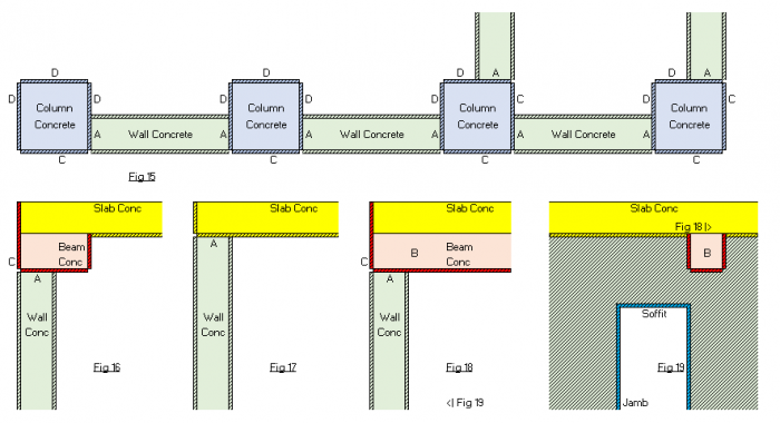
- For measurement purposes, non-structural concrete walls are deemed to be cast after casting the columns, beams and slabs.
- Formwork to columns, beams and slabs at junctions with walls (A below) is NOT deducted.
- Wall concrete and formwork at junctions with beams crossing over (B below) are DEDUCTED.
- Formwork to columns, beams and slabs on the same plane as wall formwork (C above) is NOT measured as the wall formwork.
STRUCTURAL WALLS
- Rules
- Refer to those shown on structural framing plans.
- Include attached columns and lintol beams whose cross-sections project from structural walls. (#)
- Include kickers.
- Include columns whose width > 4 x thickness.
- Measure the height of concrete and formwork from the base level of a wall to:
- top of slab above (i.e. wall measured through slab); or
- soffit of transfer structure (slab or beam) above; or
- open top of wall.
- Exclude concrete at junctions with slabs of same concrete grade (i.e. slab measured across wall).
- Exclude formwork intersected by slabs.
- Do not exclude formwork intersected by beam ends.
- Measurement Approach
- Measure wall by overall area along the centre line first
- Multiply the area by thickness to get concrete volume.
- Multiply the area by 2 to get formwork area.
- Deduct formwork intersected by slabs.
- Adjust for other items.
- Coding example: WA-40/20-250-S2-F2 = A m2
- meaning structural wall : Grade 40/20 : 250 mm thick : sloping on two faces : F2 formwork = A m2.
- generating:
- Reinforced concrete Grade 40/20 in: wall; 250 mm thick = A x 0.25 m3.
- F2 formwork to: side of wall; sloping = A x 2 m2.
- "40/20W" can be used to mean watertight
- "S2-F2" can be omitted for default cases
- "S1" can be used to mean sloping on one face only.
Concrete;
- normal | watertight | watertight with additive stated;
- plain | plain vibrated | reinforced (deemed vibrated);
- grade stated;
in:
- Wall | Hangar wall:
- normal | casing to structural steel work;
- thickness stated
- Cube
Formwork;
- normal | to produce a formed finish, finish stated;
- normal | left-in | permanent, kind and quality of materials and propping requirements stated;
to:
- Side of wall (include side of attached column):
- vertical | sloping | curved | curved in more than 1 direction, details stated;
- normal | on one face of wall only, wall thickness and background to other face stated
- Sup
- Side and soffit of lintol beam projection:
- beam itself horizontal | sloping (i.e. on any face) | curved (i.e. on any face) | curved and sloping;
- normal | on one face of wall only, wall thickness and background to other face stated
- Sup
- End of wall and end of lintol beam:
- vertical | sloping | curved | curved in more than 1 direction, details stated
- Sup
- Sloping top of wall exceeding 15° (if no adjoining slab) | Jambs and soffit of wall opening > 1.00 m2:
- straight | curved | curved in more than 1 direction, details stated
- Sup
- Boxing for wall opening size 0.025 - 0.10 m2 | 0.10 - 1.00 m2 in stages of 0.10 m2 (HKSMM4) :
- Boxing for wall opening size 0.50 - 1.00 m2 in stages of 0.10 m2 (HKSMM4R) :
- wall thickness (stated)
- Nr
COLUMNS
- Rules
- Refer to isolated columns not attached to structural walls.
- Include kickers.
- Exclude columns whose width > 4 x thickness.
- Measure the height of concrete and formwork from the base level of a column to:
- top of slab above (i.e. column measured through slab); or
- soffit of transfer structure (slab or beam) above; or
- open top of column.
- Exclude concrete at junctions with slabs of same concrete grade (i.e. slab measured across column).
- Exclude formwork intersected by slabs
- Do not exclude formwork intersected by beam ends.
- Measurement Approach
- Measure overall column length of each type first.
- Multiply the length by the cross-sectional size to get the concrete volume
- Multiply the length by the girth to get the formwork area.
- Deduct concrete at junctions with slabs of same concrete grade (i.e. slab measured across column).
- Deduct formwork intersected by slabs.
- Adjust for other items.
- Coding example: e.g. CL-40/20-400x600-F2 = L m2
- meaning column : RC Grade 40/20 : 400 x 600 mm : F2 formwork = L m2
- generating:
- Reinforced concrete Grade 40/20 in: column = L x 0.40 x 0.60 m3.
- F2 formwork to: side of column = L x (0.40 + 0.60) x 2 m2.
- "F2" can be omitted for default cases
Concrete;
- normal | watertight | watertight with additive stated;
- plain | plain vibrated | reinforced (deemed vibrated);
- grade (stated);
in:
- Column:
- normal | casing to structural steel work (# special rules to be stated for voids of large hollow sections)
- Cube
Formwork;
- normal | to produce a formed finish, finish stated;
- normal | left-in | permanent, kind and quality of materials and propping requirements stated;
to:
- Side of column:
- vertical | sloping | curved, radius stated | curved in more than 1 direction, details stated
- Sup
- Sloping top of column exceeding 15° (if no adjoining slab or beam):
- straight | curved | curved in more than 1 direction, details stated
- Sup
BEAMS
- Rules
- Refer to those suspended.
- Exclude lintol beams to structural walls.
- Measure lengths of beam concrete or formwork up to near faces of supporting structural concrete members or cantilevered ends.
- Measure depths of upstand beam concrete or formwork below the soffits of slabs.
- Measure heights of upstand beam concrete or formwork above the tops of slabs.
- Measure full depths for beam concrete only if beam concrete is of higher concrete grade than slab concrete.
- Do not deduct formwork intersected by secondary beam ends.
- Measurement Approach
- Measure overall beam length of each type first.
- Multiply length by cross-sectional size to get concrete volume.
- Multiply length by girth of two sides and soffit to get formwork area.
- Deduct slab soffit formwork intersected by beam.
- Adjust for other items.
- Coding example: BM-30/20-300x600-120-S-F2 = L m
- meaning Beam - RC Grade 30/20 - 300 x 600 mm designed size - 120 mm slab - sloping - F2 formwork = L m.
- generating:
- Reinforced concrete Grade 30/20 in: beam; sloping = L x 0.30 x (0.60 – 0.12) m3.
- F2 formwork to: sides and soffit of beam; sloping = L x (0.30 + (0.60 – 0.12) x 2) m2.
- Beam soffit area for deduction from slab soffit, provided soffit height within the same stage = L x 0.30 m2.
- “-S-F2" can be omitted for default cases.
- "UB-30/20-300x600-120/200-S" can be used to mean upstand beam in 120 mm slab with 200 mm upstand.
Concrete;
- normal | watertight | watertight with additive stated;
- plain | plain vibrated | reinforced (deemed vibrated);
- grade stated;
in:
- Beam (i.e. downstand or upstand portion)|Isolated beam (i.e. without slab):
- normal | casing to structural steel work (# special rules to be stated for voids of large hollow sections);
- horizontal | top sloping ≤ 15° | top sloping > 15°
- Cube
- Extra for shoulder of higher grade (stated) at junction with walls and columns (HKSMM4 only. Not measured if HKSMM4R.)
- Cube
Formwork;
- normal | to produce a formed finish, finish stated;
- normal | left-in | permanent, kind and quality of materials and propping requirements stated;
to:
- Sides and soffit of beam (i.e. downstand portion, include slab edge or step in slab soffit flush with beam side) | Sides and soffit of isolated beam:
- beam itself horizontal | sloping (i.e. on any face) | curved (i.e. on any face) | curved and sloping;
- beam depth 0 – 750 mm below soffit of slab | > 750 mm below soffit of slab (HKSMM4 only);
- beam depth 0 – 1.00 m below soffit of slab | > 1.00 m below soffit of slab (HKSMM4R);
- soffit height 0 – 3.50 m above support below | > 3.50 m above support below, in stages of 1.50 m | special, e.g. above lift shaft, details stated
- Sup
- Sides of upstand beam (include slab edge or step in slab top flush with beam without downstand portion):
- beam itself horizontal | sloping (i.e. on any face) | curved (i.e. on any face) | curved and sloping
- Sup
- End of beam (include slab edge) |Sloping top of beam exceeding 15° (if no adjoining slab):
- straight | curved | curved in more than 1 direction, details stated
- Sup
SLABS
- Rules
- Refer to those suspended.
- Include landings at floor levels.
- Measure slab concrete across structural walls, columns and beams of lower or same concrete grade, otherwise measure between structural walls, columns and beams.
- Deduct formwork intersected by structural walls, columns and beams.
- Measurement Approach
- Measure each type of slab areas across structural walls, columns and beams first.
- Covert to concrete volume by multiplying the areas by respective slab thicknesses.
- Adopt the slab areas as the soffit formwork areas.
- Deduct concrete at junctions with structural walls or columns of higher concrete grade (preferably when measuring structural walls, columns and beams).
- Deduct formwork intersected by structural walls, columns and beams (preferably when measuring structural walls, columns and beams).
- Adjust for other items.
- Coding example: SL-30/20-120-S-F2-H5.0 = A m2
- meaning Slab - R C Grade 30/20 - 120 mm thick - top sloping - F2 formwork - soffit height 3.50 - 5.00 m = A m2.
- generating:
- Reinforced concrete Grade 30/20 in: slab; 120 mm thick; top sloping > 15° = A x 0.12 m3.
- F2 formwork to: soffit of slab; 0 - 200 mm thick; sloping; soffit height 3.50 - 5.00 m = A x 2 m2.
Concrete;
- normal | watertight | watertight with additive stated;
- plain | plain vibrated | reinforced (deemed vibrated);
- grade (stated);
in:
- Slab | coffered and troughed slab (exclude volume occupied by moulds, measure margin >= 500 mm wide as slab):
- thickness of slab stated | overall thickness of coffer and trough slab stated;
- horizontal | top sloping ≤ 15° | top sloping > 15°
- Cube
- Extra for shoulder of higher grade (stated) at junction with walls and columns
- Cube
Formwork;
- normal | to produce a formed finish, finish stated | metal deck;
- normal | left-in | permanent, kind and quality of materials and propping requirements stated;
to:
- Soffit of slab:
- slab thickness 0 – 200 mm | > 200 mm in stages of 100 mm;
- horizontal | sloping | curved | curved in more than 1 direction, details stated;
- soffit height 0 – 3.50 m above support below | > 3.50 m above support below, in stages of 1.50 m | special, e.g. above lift shaft, details stated
- Sup
- Soffit of coffered and troughed slab (plane area measured):
- overall thickness of coffer and trough slab stated, sizes of moulds and profile, centres of moulds stated;
- horizontal | sloping | curved | curved in more than 1 direction, details stated;
- soffit height 0 – 3.50 m above support below | > 3.50 m above support below, in stages of 1.50 m | special, e.g. above lift shaft, details stated
- Sup
- Sloping top of slab exceeding 15°:
- straight | curved | curved in more than 1 direction, details stated
- Sup
- Edge of slab | Step in top of slab | Step in soffit of slab (i.e. those not flush with side of beam):
- straight | curved | curved in more than 1 direction, details stated
- Sup
- Boxing for slab opening size 0.025 - 0.10 m2 | 0.10 - 1.00 m2 in stages of 0.10 m2 (HKSMM4) :
- Boxing for slab opening size 0.50 - 1.00 m2 in stages of 0.10 m2 (HKSMM4R) :
- slab thickness (stated)
- Nr
NON-STRUCTURAL WALLS (EXTERNAL WALLS AND INTERNAL WALLS KEPT SEPARATE)
- Rules
- Refer to those shown on architectural plans but not on structural framing plans.
- Include kickers.
- Measure non-structural walls and features as if structural walls, columns and beams have been cast.
- Measure the concrete volume or formwork area bounded by slabs, beams, structural walls and columns.
- Exclude concrete volume or formwork area intersected by beams.
- Do not deduct formwork to slabs, beams, structural walls and columns intersected by non-structural walls as if the structural members are cast before casting the non-structural members. (#)
- Exclude formwork intersected by non-structural walls.
- Measurement Approach
- Measure wall area along the centre line of each type first.
- Deduct from area junctions with beams.
- Multiply the area by thickness to get concrete volume.
- Multiply the area by 2 to get formwork area.
- Deduct formwork at T-junctions of non-structural walls.
- Adjust for other items.
- Coding example: EW-20/20-120-S2-F2 = A m2
- meaning External wall - RC Grade 20/20 - 120 mm thick - sloping - F2 formwork = A m2.
- generating:
- Reinforced concrete Grade 20/20 in: wall; 120 mm thick = A x 0.12 m3.
- F2 formwork to: side of wall; sloping = A x 2 m2.
- Use "IW" for internal walls.
- "20/20W" can be used to mean watertight.
- "-S2-F2" can be omitted for default cases.
- "-S1" can be used to mean sloping on one face only.
Concrete;
- normal | watertight | watertight with additive stated;
- plain | plain vibrated | reinforced (deemed vibrated);
- grade stated;
in:
- Wall | Hangar wall:
- normal;
- thickness stated
- Cube
Formwork;
- normal | to produce a formed finish, finish stated;
- normal | left-in | permanent, kind and quality of materials and propping requirements stated;
to:
- Side of wall:
- vertical | sloping | curved | curved in more than 1 direction, details stated;
- normal | on one face of wall only, wall thickness and background to other face stated
- Sup
- End of wall:
- vertical | sloping | curved | curved in more than 1 direction, details stated
- Sup
- Sloping top of wall exceeding 15° (if no adjoining slab) | Jambs and soffit of wall opening > 1.00 m2:
- straight | curved | curved in more than 1 direction, details stated
- Sup
- Boxing for wall opening size 0.025 - 0.10 m2 | 0.10 - 1.00 m2 in stages of 0.10 m2 (HKSMM4) :
- Boxing for wall opening size 0.50 - 1.00 m2 in stages of 0.10 m2 (HKSMM4R) :
- wall thickness (stated)
- Nr