Building Information Modelling 建築信息模型 / 建築資訊模型
Building Information Modelling 建築信息模型 / 建築資訊模型 KCTangBIM = Building Information Modelling = Modelling of Information of Building = 3D graphical model + information.
CAD = Computer aided design.
Apart from the 3D graphical part implied by the term "model", the feature rich information part distinguishes BIM from CAD.
4D BIM = 3D graphical model & information + time information.
5D BIM = 4D BIM + cost information.
6D BIM = 5D BIM + facility management information.
QTO = quantity take-off = measurement of quantities.
Revit is one of BIM software.
Development Bureau Technical Circular (Works) No. 18/2018
Development Bureau Technical Circular (Works) No. 18/2018 KCTangNote
3 July 2019: First created.
Title of Circular
Adoption of Building Information Modelling for Capital Works Projects in Hong Kong.
Dates
Issued: 27 December 2018.
Effective: 1 January 2019.
Superseding DEVB TC(W) No. 7/2017.
Scope
Policy and requirements on the adoption of BIM techmology in public works projects either by government staff, consultants or contractors.
Policy
BIM to be used on capital works projects estimated to cost more than HK$30 Million.
Irrespective of the modes of delivery.
Purposes
Enhance productivity.
Reduce risks and costs.
Optimize operation and maintenance.
Investigation, Feasibility and Planning Stage
Optional, depending on the perceived benefits.
Design Stage
Mandatory for designs under:
- Design and Construction consultancy agreements
- Investigation, Design and Construction consultancy agreements
- all in-house projects.
Construction Stage
Mandatory.
At least an as-built BIM model for contracts not adopting BIM in the design.
Applicable to design-bid-build, design-build, design-build-operate projects.
Asset Management
Works departments to critically review their departmental asset management strategy in order to leverage the technology to enter into the digital built environment.
Entrustment Projects, Sub-vented Projects and Private Projects to be Handed Over to Government
Entrusted projects within Government departments - same policy.
Projects entrusted to organisations outside Government (Airport Authority, MTR Corporation Limited, private developers, etc.), sub-vented projects and private projects to be handed over to the Government - align with the BIM adoption/implementation policy of the organisations, but Works Departments to encourage.
Mandatory BIM Uses
IFP = Investigation, Feasibility and Planning
D = Design
C = Construction
M = Mandatory
M = Mandatory for all T&F proposals or construction works tenders invited on or after 1 January 2019
O = Optional
Use = See the latest version of the BIM Standards of the Construction Industry Council for explanations.
|
BIM Use |
IFP |
D |
C |
|
|
1 |
Design authoring |
O |
M |
M |
|
2 |
Design reviews |
O |
M |
M |
|
3 |
Existing conditions modelling |
O |
M |
M |
|
4 |
Site analysis |
O |
M |
|
|
5 |
3D coordination |
M |
M |
|
|
6 |
Cost estimation |
O |
Ma |
Mb |
|
7 |
Engineering analysis |
O |
O |
|
|
8 |
Facility energy analysis |
O |
O |
|
|
9 |
Sustainability evaluation |
O |
O |
O |
|
10 |
Space programming |
O |
Mc |
|
|
11 |
Phase planning (4D Modelling) |
Md |
M |
|
|
12 |
Digital fabrication |
O |
Me |
|
|
13 |
Site utilization planning |
Mf |
||
|
14 |
3D control and planning |
O |
||
|
15 |
As-built modelling |
M |
||
|
16 |
Project systems analysis |
O |
||
|
17 |
Maintenance scheduling |
Mg |
||
|
18 |
Space management and tracking |
O |
||
|
19 |
Asset management |
O |
||
|
20 |
Drawing generation (drawing production) |
M |
M |
a. Mandatory for project cost budgeting, project cost control and cost evaluation on design options, etc. at design stage as far as practicable.
b. Mandatory for project cost control, cost evaluation on variation of works, cash flow/spending analysis, etc. at construction stage as far as practicable.
c. Mandatory for checking client spatial requirements such as compliance with the approved schedule of accommodations, reference plot ratio for building projects and site coverage of greenery for building projects, or other spatial requirements relevant to building/civil projects as considered appropriate.
d. Mandatory for the construction activities with very high to extreme risk level identified from the Systematic Risk Management (SRM) according to ETWB TC(W) No. 6/2005 or other activities as considered appropriate at design stage.
e. Mandatory for digitalizing the construction details in the BIM model for mass customized components such as metal cladding, acoustic panels, building façade panels, ceiling panels, acoustic barriers, metal structural members, etc. which are of large quantities and variety in dimensions, shapes, geometries, etc.
f. Mandatory for the construction activities with very high to extreme risk level identified from the SRM according to ETWB TC(W) No. 6/2005 or other activities as considered appropriate at construction stage.
g. Mandatory for providing maintenance attributes for facility structures, fabrics and equipment in the as-built models as considered appropriate.
Exceptional Grounds for Exemption
Serious contractual implications.
Substantial impact on project delivery.
Projects of little technical content, e.g.
- operation of public fill banks
- paving and painting works
- slope maintenance works
- greening works
- maintenance works under term contracts
- procurement of vehicles.
Authority for Exemption
Exemption by heads of Works Department partly or wholly.
Records to be kept and the Development Bureau to be informed of the approvals for exemptions with detailed justification.
BIM Software
Specific brand names and models of BIM software not to be specified in consultancy or works tenders, notwithstanding considerations on compatibility.
Tender specifications must be performance and function based.
Production of Two-Dimensional Drawings
2D drawings to be generated from 3D BIM models.
Cease to produce 2D drawings by other platforms if those drawings can be generated from the 3D BIM models.
2D drawings generated from the 3D BIM models need not follow "CAD Standard for Works Projects (CSWP)".
Contractual Requirements
Engagement of BIM sub-consultant or sub-contractor permitted.
In-house staff training is still required.
Consultant's/Contractor's Team Structure
A BIM team to be provided:
- appropriate for the scale and complexity of the consultancy assignment/works contract
- including sufficient and technically competent resources to complete all BIM tasks and deliverables specified in the assignment/contract
- comprising at least [3] personnel (BIM team leader and BIM coordinators) well trained in relevant disciplines.
BIM team leader
- leads the BIM team
- holds a key position in the project team structure
- either has corporate membership of an appropriate professional institution or has a minimum of 5 years relevant post-qualification experience plus university degree or equivalent in an appropriate engineering or construction related discipline
- has a minimum of 3 years practical experience in management of BIM projects
- be responsible for the overall BIM managements and process controls
BIM coordinator (more than 1)
- has a miniumum of 3 years related construction project experience
- has a minimum of 1 year practical experience in BIM project
- handles BIM tasks delegated by the BIM team leader such as BIM modelling
- collaborates information exchange amongst related stakeholders
- maintains a drawing/information register to record the information to be incorporated in the models.
Proposal highlighting key roles and responsibilities of each position to be submitted within [14] calendar days after commencement of assignment/contract.
Any proposed change of BIM team members to be notified with CV and evidence of equivalent BIM competency of the replacement to the Director/Engineer/Supervising Officer within [7] calendar days (of change?) for approval.
BIM Sub-consultant's/Sub-contractor
Engaging of BIM sub-consultant/sub-contractor permissible.
Approval to be obtained from the Director/Engineer/Supervising Officer before formal engagement.
Involvement of BIM sub-consultant/sub-contractor permissible to be clearly indicated in the project team structure.
Positions of the staff members from the BIM sub-consultant/sub-contractor to be clearly indicated in the BIM team organisation structure.
BIM Training Requirements
Consultant/Contractor to nominate his staff or (not BIM) sub-consultant's/sub-contractor's staff to attend, within [6] months from the commencement of the assignment/contract, training courses organized by the Construction Industry Council:
- [4] staff members to attend and successfully complete the Building Information Modelling Basic Modelling Courses
- [4] staff members to attend and successfully complete the Building Information Modelling discipline-specific Advanced Modelling Courses.
Nomination to be approved by the Director/Engineer/Supervising Officer before the commencement of the training course.
In case of failure of nominated staff members to complete the training course, Consultant/Contractor to arrange additional BIM training courses to his staff members to fulfil the contract requirements at his own cost.
Numbers in [ ] are for reference only and to be suitably determined by the Works Department according to the nature, scale, complexity, mode of project delivery, number of consultant/contractor/sub-consultant/sub-contractor involved, etc. of the project.
Start Revit
Start Revit KCTangStart Revit: select the Revit icon on desktop:
![]()
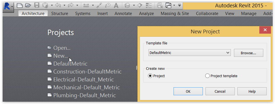
Create new project: select New > DefaultMetric, or click the various choices available:
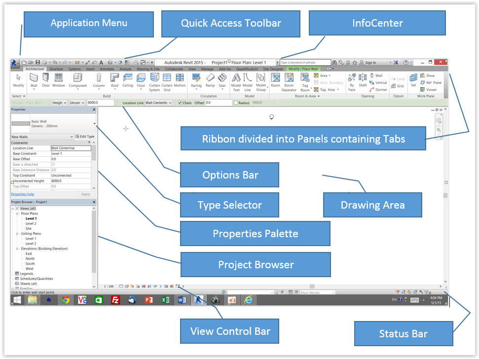
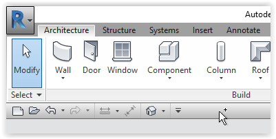
Drawing Screen:
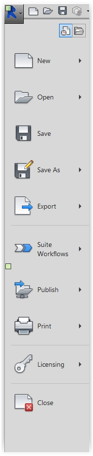
Application Menu:
Use quick access toolbar
Use quick access toolbar KCTangPosition
The toolbar can be above the ribbon:
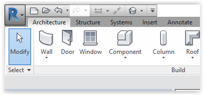
or below the ribbon:
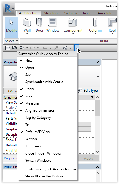
To customize
Left-click the pull down icon:
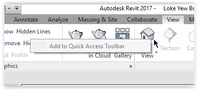
To add choices
Hoover over the desired ribbon tab > Right-click > Left-click: Add to Quick Access Toolbar:
(First posted: 31/3/2017)
Understand some terms
Understand some terms KCTangElements
Each building block or object making up a Revit model is called an element.
Each element has its own properties with values. Each of these properties is called a parameter.
Elements are grouped by Discipline > Category > Family > Type > Instance.
An instance is a single element. Each element shares the same Family Parameters which can be overridden by Type Parameters which can be overridden by Instance Parameters.
Parametric modelling
The parameters can be viewed and some may be edited through a Properties window.
Apart from drawing graphically, by changing the values of the parameters, the elements can be changed and consequently the model can be changed. Therefore, BIM is called "parametric modelling".
More parameters can be added. The values of the parameters constitute the "Information" part of Building Information Modelling.
Disciplines
Architecture
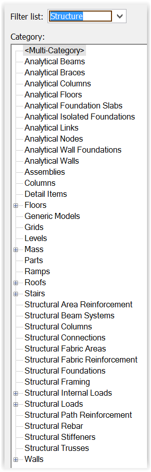
Structure
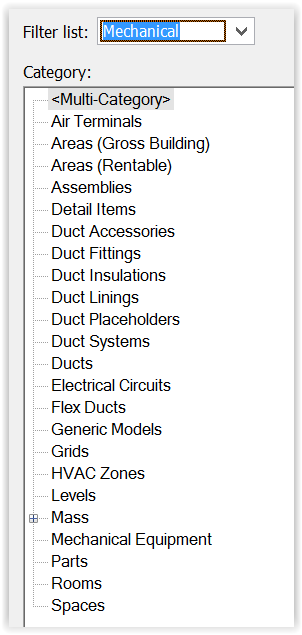
Mechanical
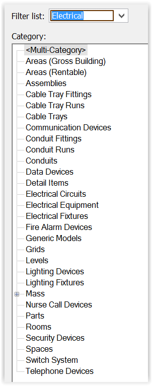
Electrical
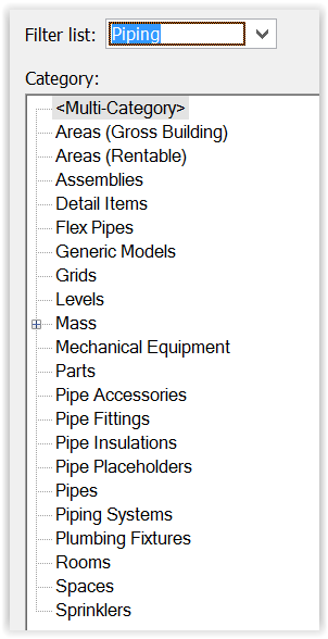
Piping
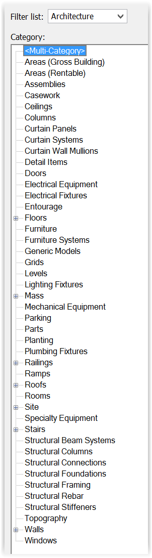
Categories
Architecture:
Structure:
Mechanical:
Electrical:
Piping:
Families and Types
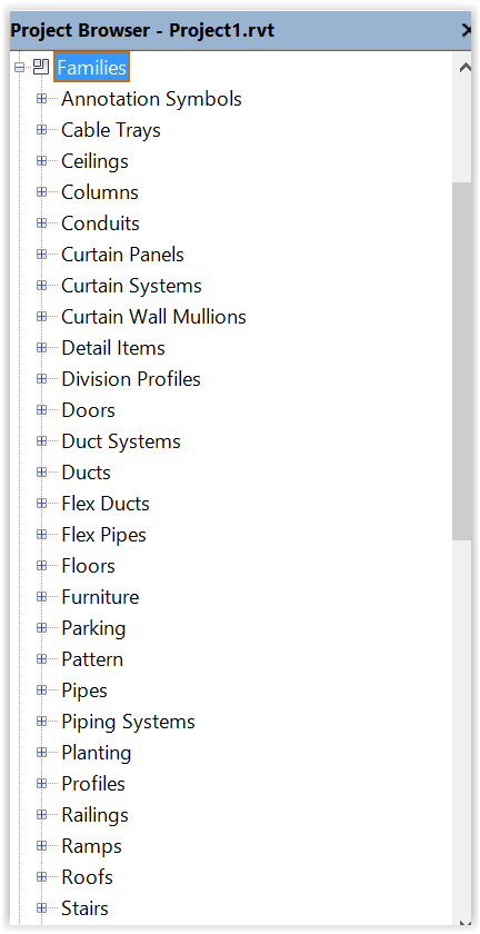
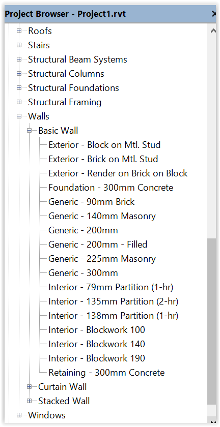
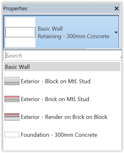
In the following Project Browser, "Walls" is a category under which are families of Basic Wall, Curtain Wall and Stacked Wall. Under the Basic Wall family, there are various types of walls, such as Generic, Exterior, Interior, etc.:
Use mouse and keyboard
Use mouse and keyboard KCTangMouse
Zoom in and out the model: Move the middle wheel of the mouse up or down.
Pan left, right, up or down: Press the middle wheel and move the mouse to the left, right, up or down.
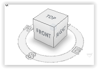
Rotate (orbit) 3D model: Press keyboard Shift, and at the same time press the middle wheel and move the mouse to the left, right, up or down.
Selection
Left-click: to select an item.
Left-click and drag mouse to draw a rectangular: to select a graphical region.
Alt key: to switch between graphical items nearby.
Ctrl + Left-click: to add another item to selection.
Shift + Left-click: to unselect an item.
Keyboard shortcuts
Esc to end a continuous series of actions.
(alternatively  )
)
Ctrl-Z = undo an action.
(alternatively 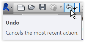 and
and 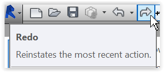 )
)
ZR and use  to select the region = Zoom in Region.
ZO = Zoom Out.
ZF = Zoom to Fit.
ZA = Zoom All to Fit.
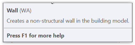
The tool-tip help also shows the keyboard shortcuts for some of the menu items, e.g. WA for Wall:
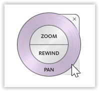
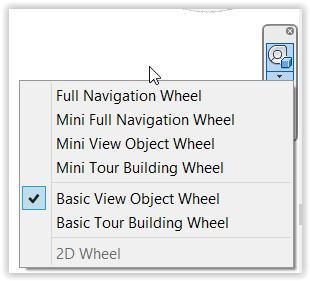
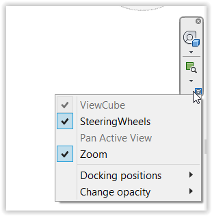
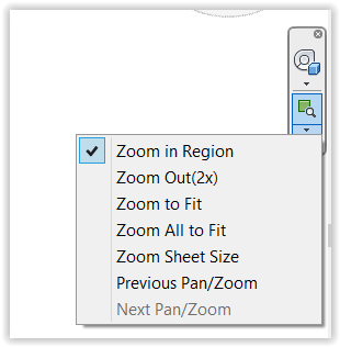
Wheels and Viewcubes
2D wheel:
Full netvigation wheel:
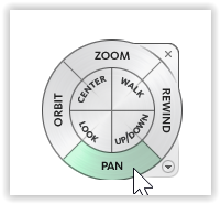
Basic view object view:
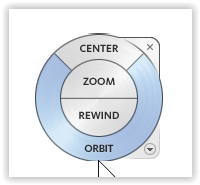
Netvigation wheel menu to choose between different types of wheels:
Netvigation bar menu:
Zoom menu:
3D View cube:
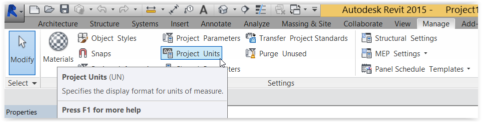
Set up project units
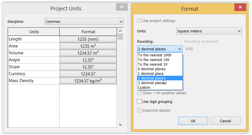
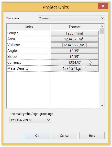
Set up project units KCTangSet up the format of Area and Volume to hide their units but use 2 decimal places to represent Area and 3 decimal places to represent Volume
This change eliminates the need to remove the units when using Excel for further calculations after the area and volume are exported from the Schedules to Excel files.
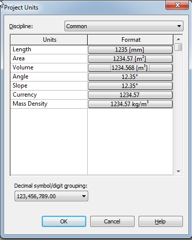
Left-click: Manage Ribbon > Project Units Tab:
The Properties pallete shows up. Units shown within "[ ]" will be hidden on display:
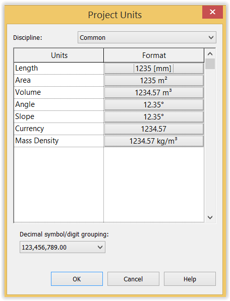
Left-click: Format of Area:
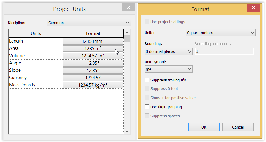
Left-click: Rounding > 2 decimal places to change format of Area to 2 decimal places without unit:
Left-click: Unit symbol > None > OK:

Left-click: Format of Volume:
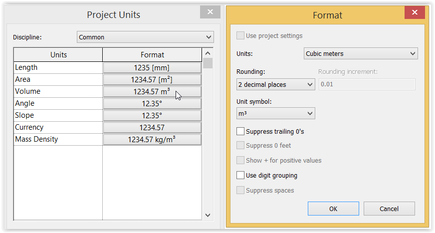
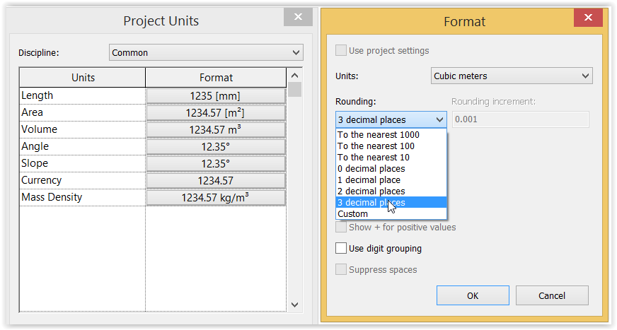
Left-click: Rounding > 3 decimal places to change format of Volume to 3 decimal places without unit:
Left-click: Unit symbol > None > OK:
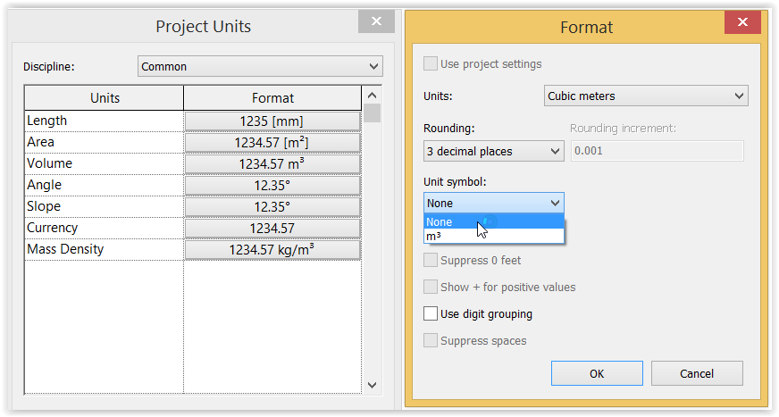
Left-click: OK to finish:
Draw grids
Draw grids KCTangDraw vertical grid lines (do not care too much about the exact spacing for the time being)
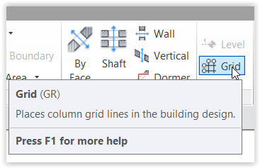
Left-click: Architecture or Structure > Datum - Grid:
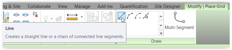
Left-click: Draw - Line to draw free hand straight line:
Start from right to left if grid line references are to start from the right.
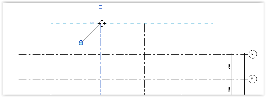
Left-click drawing area > Move mouse down to draw a vertical line:
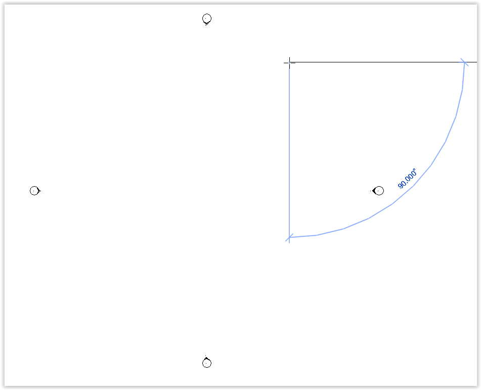
Left-click to end the line:
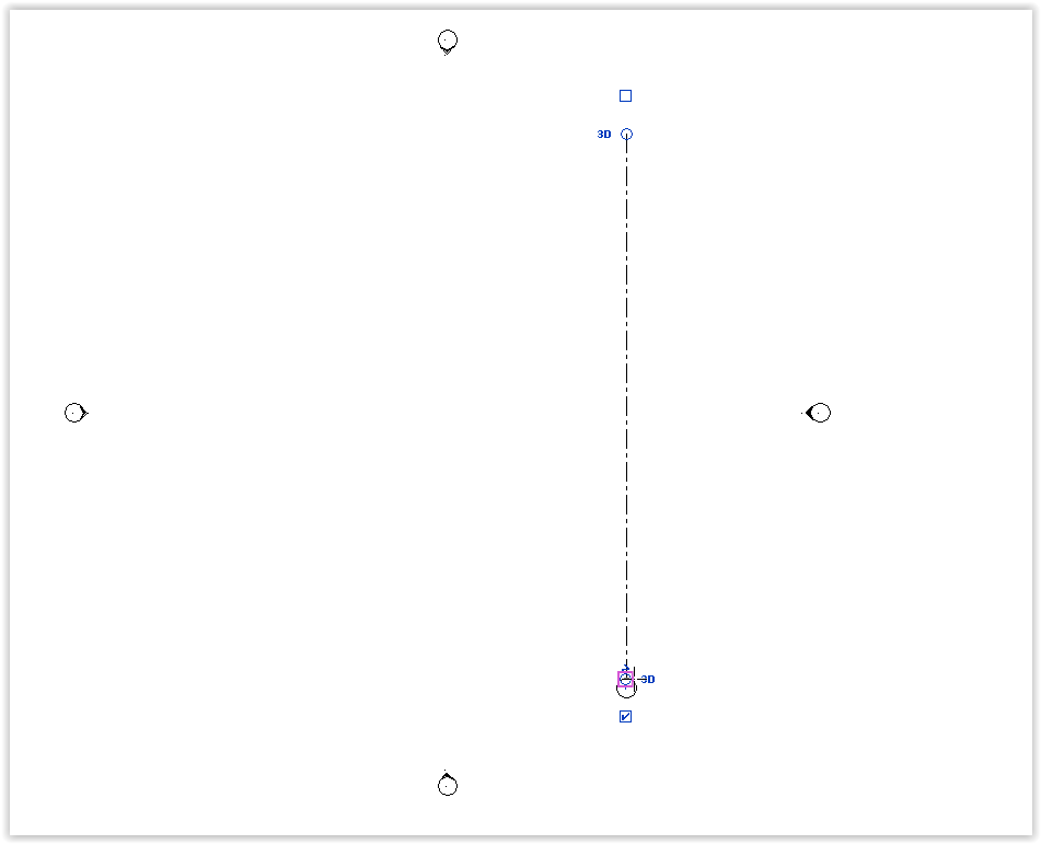
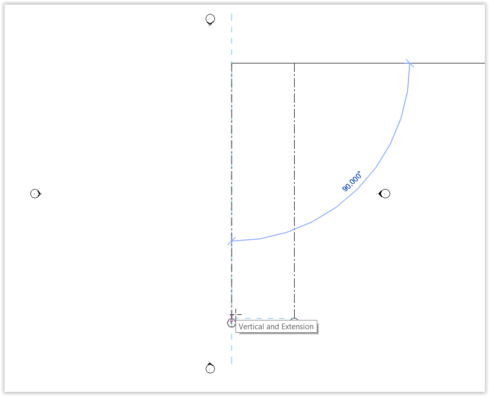
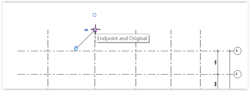
Move mouse to the left > Align with the help of the blue horizontal line with the first grid line:
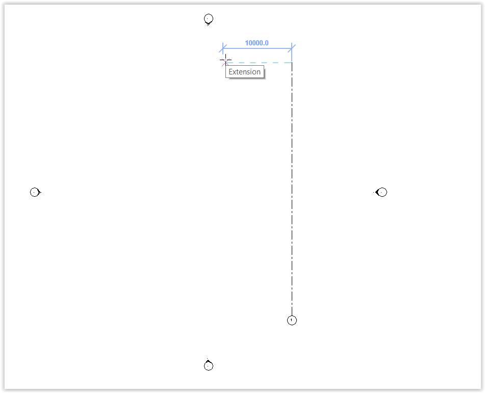
Move mouse down to draw a vertical line with the end to align with the end of the first grid line > Left-click to end the line:
Continue to draw other lines > press Esc to finish the current command.
Change spacing between two lines (however, better use annotated dimensions to change spacing, as described later)
Left-click: body (not end) of the line to be moved (e.g. grid l2 below) > dimension on the right (e.g. 12000.0 below) > Change the dimension (e.g. 5000.0):
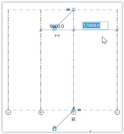
Note: Since grid 2 is drawn after grid 1, its position is relative to grid 1, only "12000.0" can be selected to be changed. "9000.0" cannot be selected to be changed.
Positions after change:
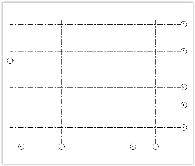
Draw horizontal grid lines
Like drawing the vertical grid lines, draw lines from left to right.
Start from bottom to top if grid line references are to start from the bottom:
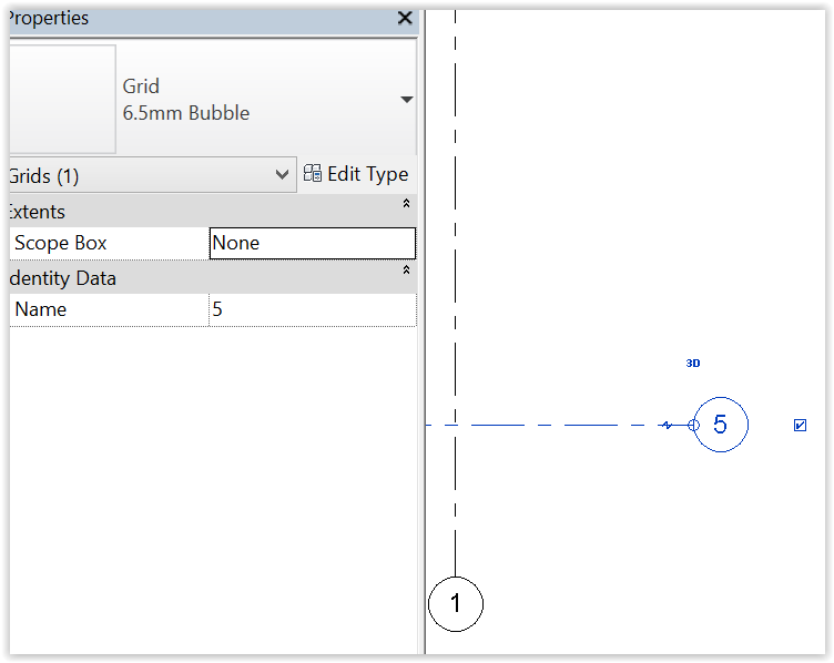
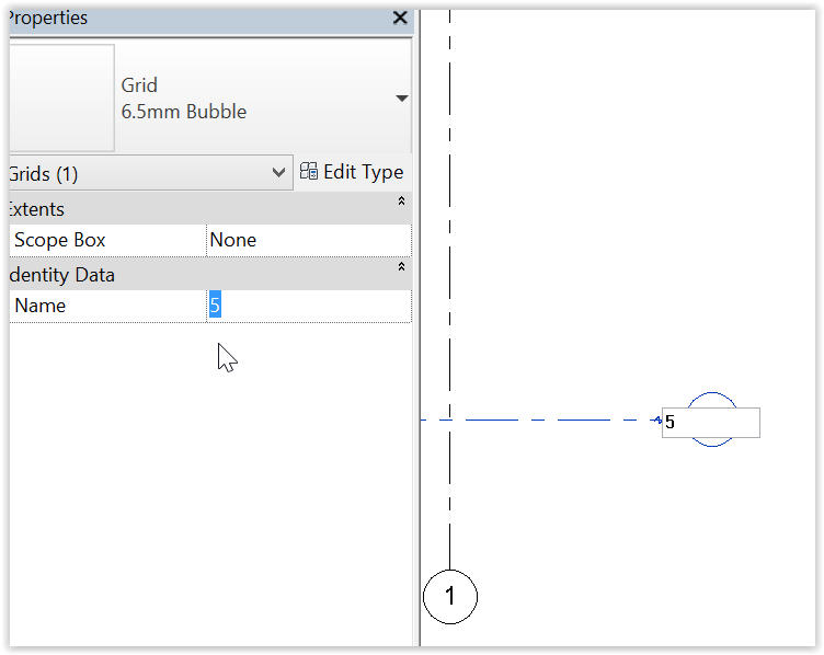
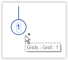
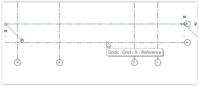
Change grid line reference to start from "A" instead of "5": Left-click: body of the line > reference in the bubble > Change the reference > Enter > Esc:

Alternatively, Left-click: body of line > Name property > Change the reference > Enter > Esc:
Finished result before pressing Esc:
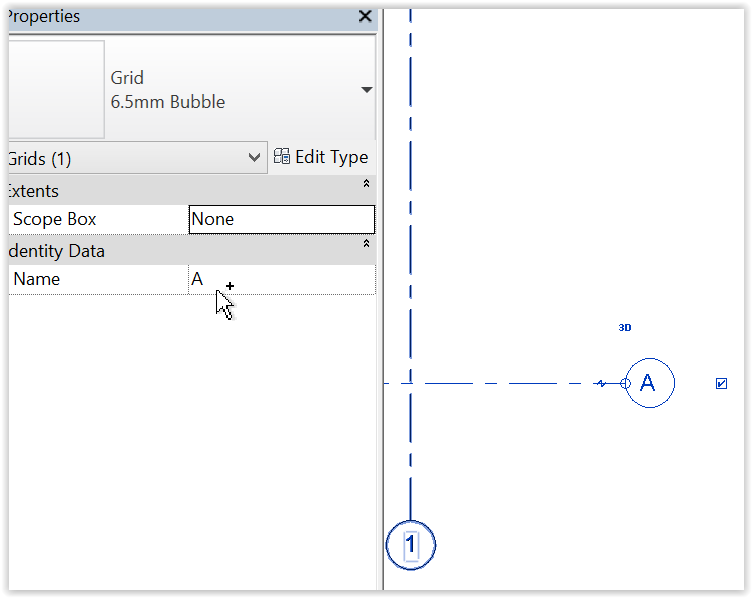
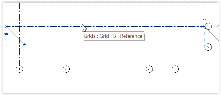
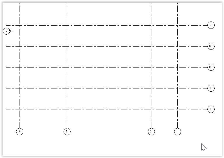
Continue drawing other lines will have references of C, D, E, etc.:
Showing or hiding bubbles
Reference bubbles will appear at the end of the grid line being drawn:
To show the bubble at the other end: Left-click: body of the line to display a square box from the end of the line:
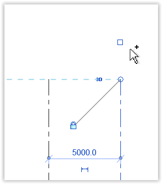
Left-click: the square box to display the reference in the bubble:
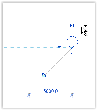
If desired, deselect the square box to hide the reference in the bubble.
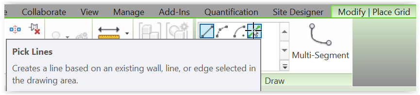
Use pick lines and offset
Use pick lines and offset KCTangNote
Revit provides a Pick Lines option for various drawing commands.
Pick Lines uses an existing line as a reference and draws an identical line offsetting a specified distance from the reference line.
The following shows the use of Pick Lines to draw grid lines. The same technique can be followed for some other drawing commands.
Duplicate lines using "Pick Lines" (a quicker method after drawing the first grid line)
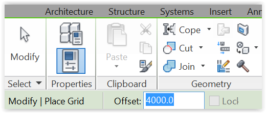
Left-click: Architecture or Structure > Datum - Grid > Draw - Pick Lines:
Change Offset to specify spacing between lines:
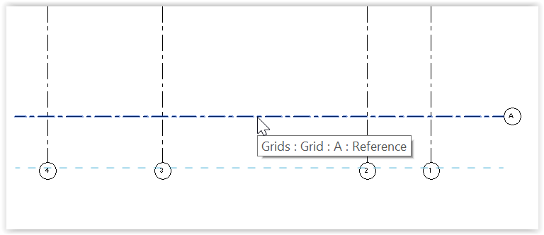
Left-click the reference grid line to fix the new line:
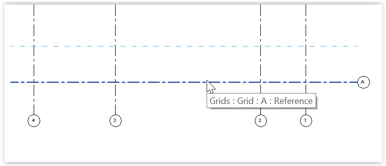
Move from the above of the second horizontal grid line > Left-click it to make it the new reference grid line and to fix the new grid line:
Repeat the action. All new grid lines will be 4000 mm from their own referenced grid lines:
Annotate with dimensions
Annotate with dimensions KCTangNote
Annotating with dimensions can adjust and control the sizes and positions of modelled objects.
Annotated dimensions will be displayed and printed. If desired, annotated dimensions can be removed after being used to adjust sizes and positions without affecting the sizes and positions already set.
The following shows an example of annotating horizontal grid lines. The techniques can be followed for annotating other modelled objects.
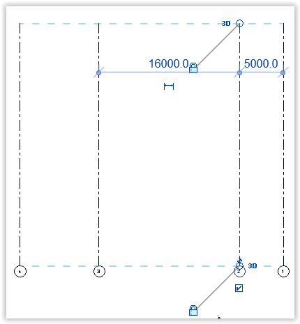
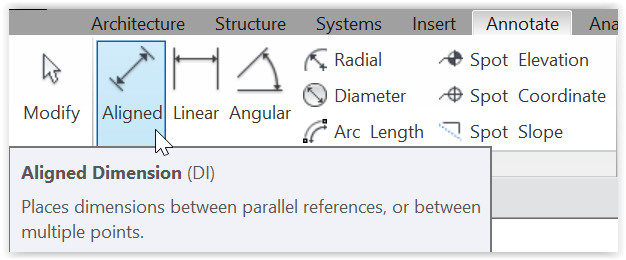
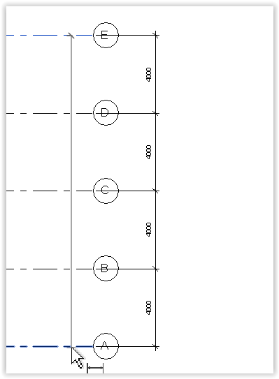
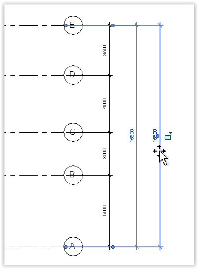
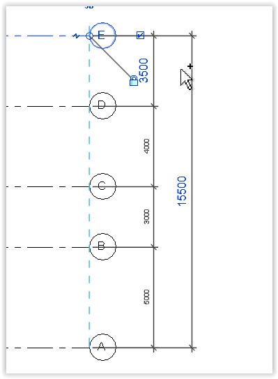
Annotate parallel grid lines with running dimensions
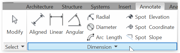
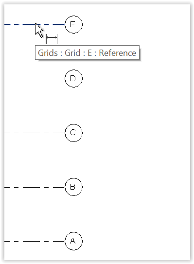
Left-click: Annotate > Dimension - Aligned:
Left-click the first line:
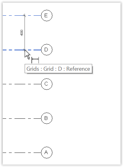
Drag down > Left-click the second line:
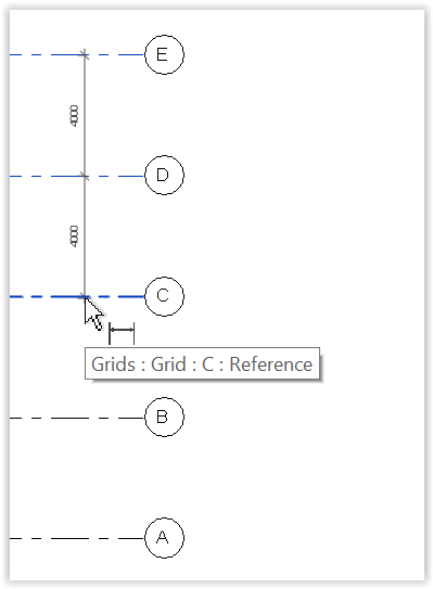
Drag down > Left-click the third line:
Drag down > Left-click the fourth line:
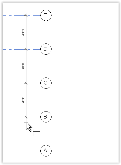
Drag down > Left-click the fifth line:
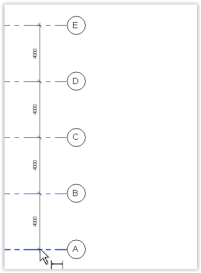
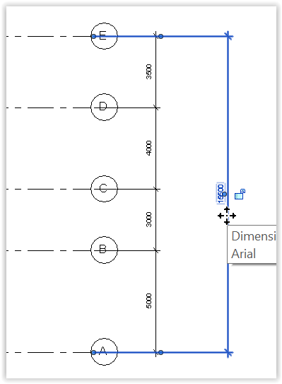
Drag left or right to move the set of running dimensions to the the left or the right (not a must) > Drag up or down the end of dimension line > Left-click any point away from the lines to be dimensioned to end the dimension line:
Left-click any point again to finish:
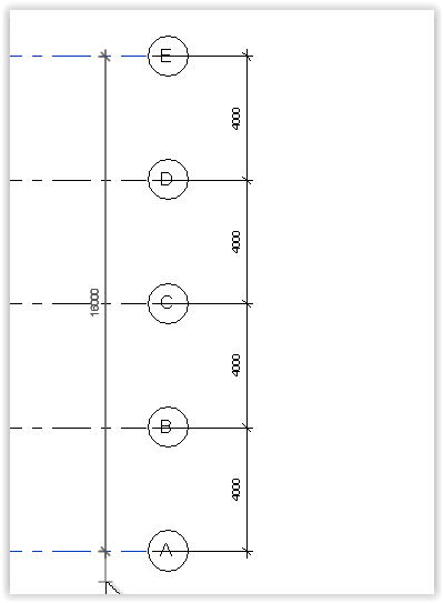
Draw overall dimension
Follow the technique above to draw the overall dimension:
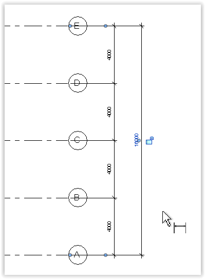
Change position of dimensions
Left-click dimenson line:
Drag left or right to move its position:
Left-click to finish:
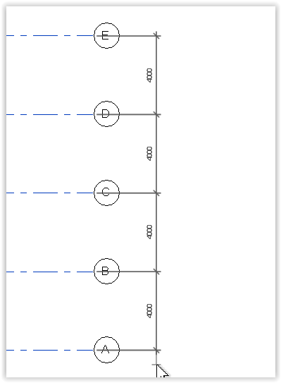
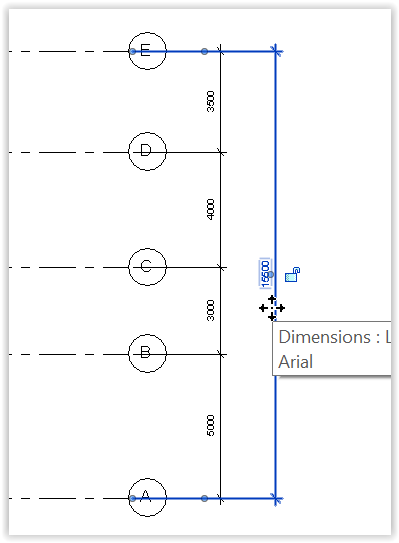
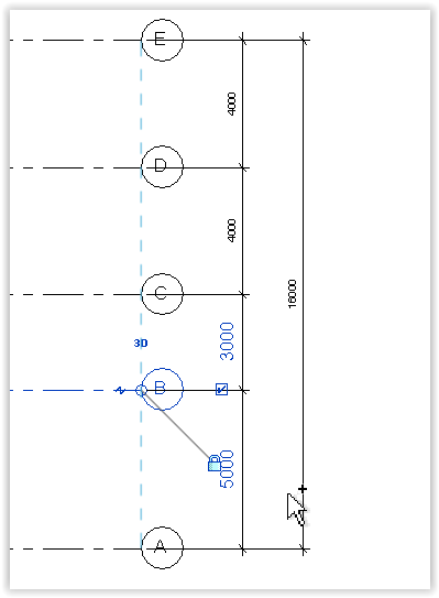
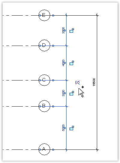
Change dimensions to move line position
Left-click the line to be moved (e.g. grid B as below, not the dimension line):
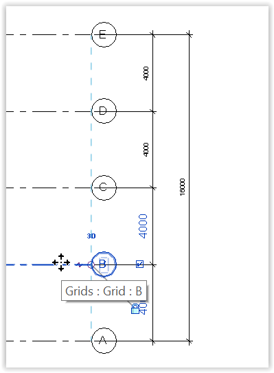
Left-click the dimension relative to grid A:
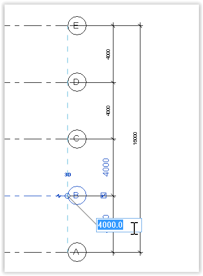
Change the dimension > Enter:
Left-click another line to be moved (e.g. grid E as below):
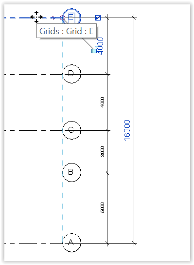
Left-click dimension:
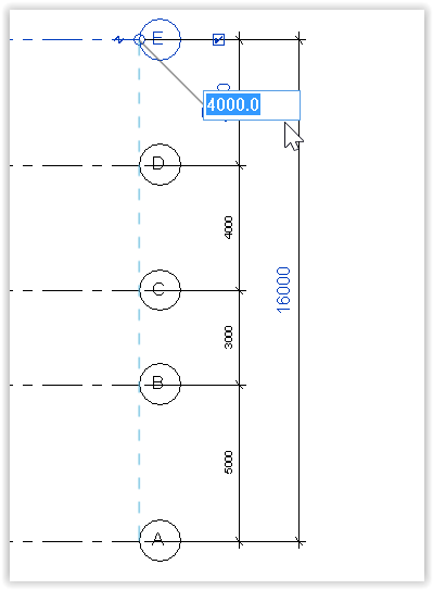
Change dimension:
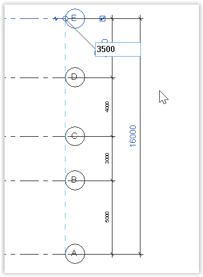
Enter > Esc to finish this series of commands:
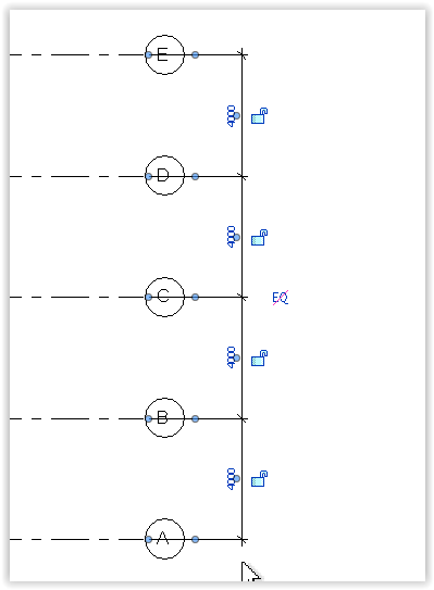
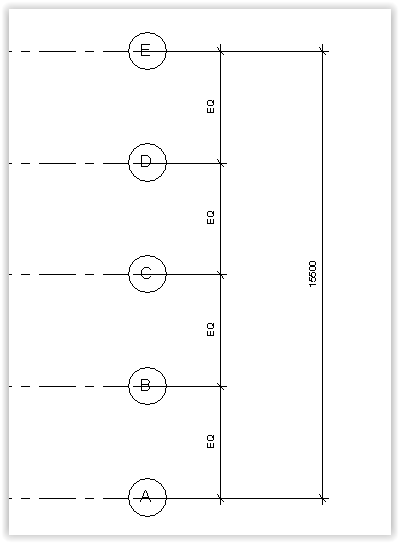
Change all lines to equal spacings
Left-click the dimension line > Look for the "EQ" sign crossed in red:
Left-click the EQ sign:
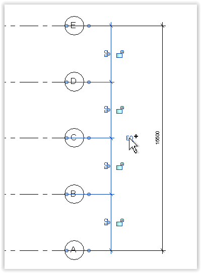
Esc to finish this series of commands:
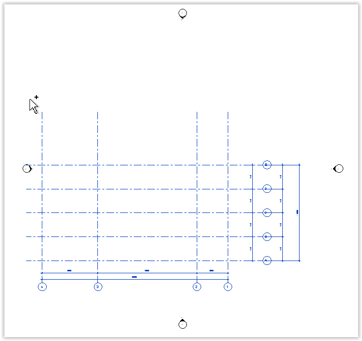
Select region
Select region KCTangNote
Selecting a region in the drawing area from left to right or from right to left will have different effects.
Proper use would enable selection of desired elements excluding other elements.
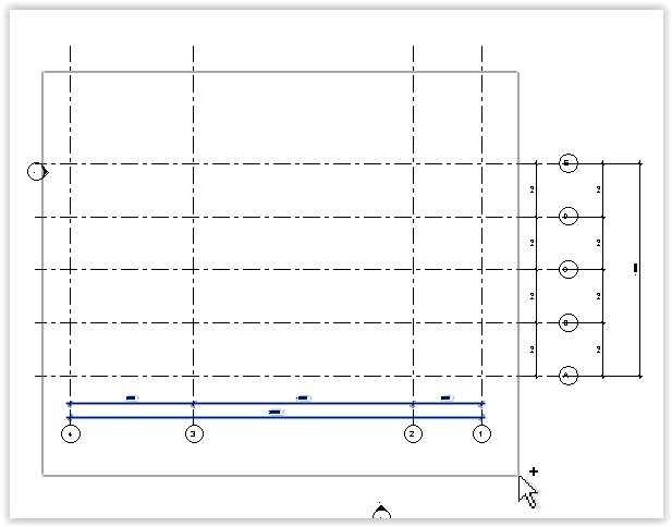
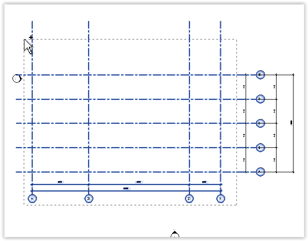
Select region from left to right
Left-click and extend upward or downward the rectangular box from left to right.
The rectangular box is in solid line.
Only elements wholly contained in the rectangular box will be selected (highlighted).
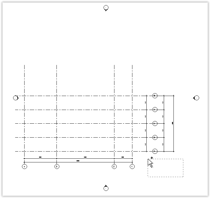
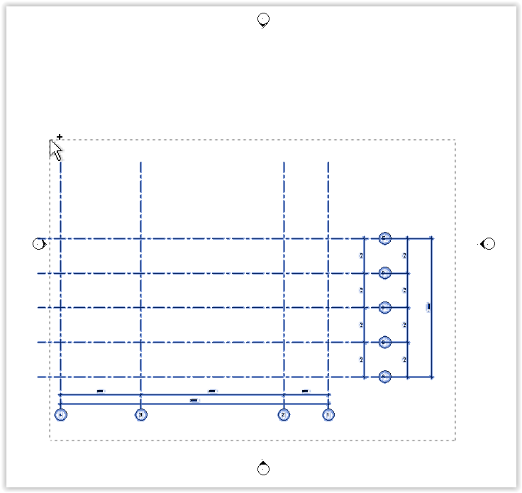
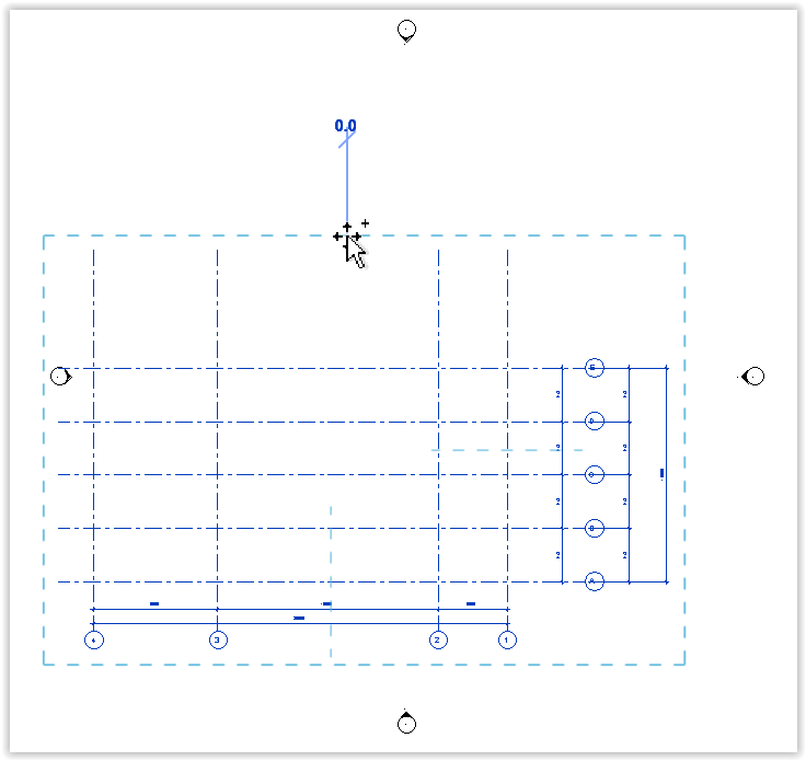
Select region from right to left
Left-click and extend upward or downward the rectangular box from right to left.
The rectangular box is in dotted line.
Any elements partly within the rectangular box will be selected (highlighted).
Move elements
Move elements KCTangMoving graphical elements
Left-click: Elements to be moved > Modify - Move > Any point in the drawing area > Another point in the drawing area > Esc to finish.

The distance and direction from the first point to the second point represent the distance and direction to be moved.
The points can be outside of the elements to be moved.
However, to move a point of the elements to a precise position, select the point as the first point and select the precise position as the second point.
Alternatively, use keyboard up, down, left and right arrows to move approximately after selection.
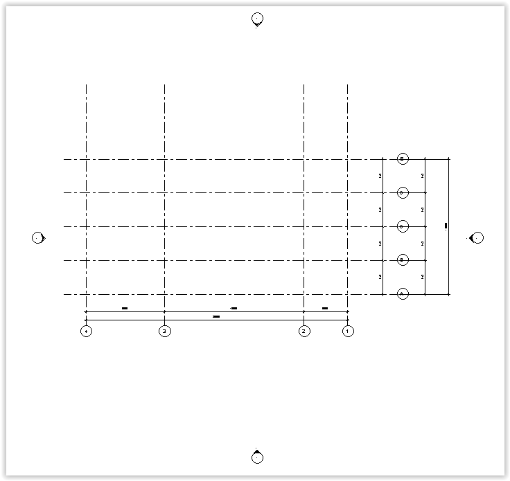
Example of moving all grid lines
Select region:
Extend the region (note elements partly falling within the rectangle will be selected and shown as blue):

Left-click to finish selection (selected elements shown in blue, but rectangle disappeared):
Left-click Modify - Move:

Note the rectangle will appear in blue.
Left-click first point:
Left-click second point > Esc to finish:

Finished:
Adjust grid length
Adjust grid length KCTangAdjust length of a group of grid lines
Left-click the body of one of the grid lines. A dotted line joining adjacent grid lines of the same lengths will appear.
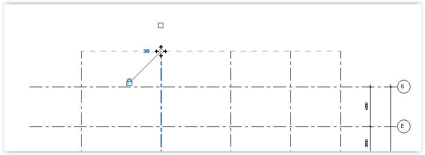
Left-click the end of the selected grid line.
Drag the end of the line. All the ends of the grid lines will be moved.
Draw walls
Draw walls KCTangSelect structural wall tool
Left-click floor plan, e.g. Level 1
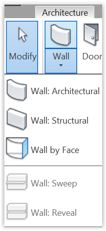
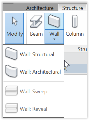
Left-click: Architecture - Wall > Wall: Structural:
or
Left-click: Structure - Wall > Wall: Structural
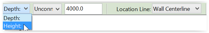
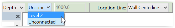
Define wall placement options
![]()
Left-click Height to draw wall from floor to ceiling:
Left-click Level 2 as the top constraint, i.e. stopping wall at Level 2 floor level:
Left-click Core Face Exterior to locate the exterior face of core of wall relative to the reference line:

Draw external walls in clockwise direction
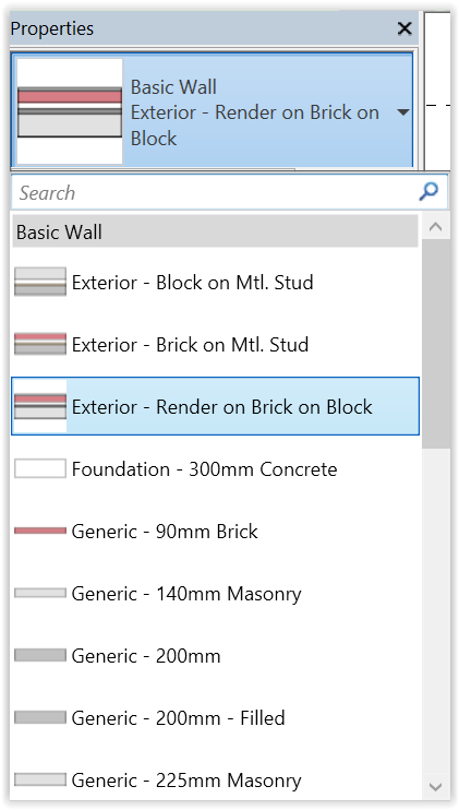
Left-click: Type Selector > Basic Wall - Exterior - Render on Brick on Block:
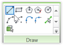
Left-click Draw - Line:
ZR > Left-click and Drag a region to zoom in to the region:
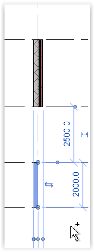
Left-click a point anywhere in the Drawing Area (e.g. on a grid intersection) > Drag downward > Left-click to end wall > Esc to finish command:
Left-click another point > Drag upward this time to draw another wall > Left-click > Esc:
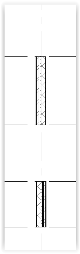
Left-click View Control Bar - Detail Level: Medium to see the component layers of the wall:
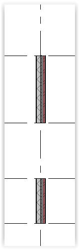
Note that the walls face different directions.
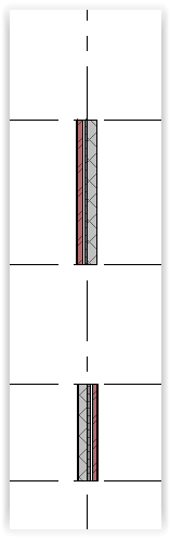
Left-click View Control Bar - Visual Style: Shaded to see the wall orientation clearer:
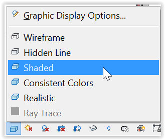
This demonstrates that external walls should be drawn in clockwise direction to make them face outward.
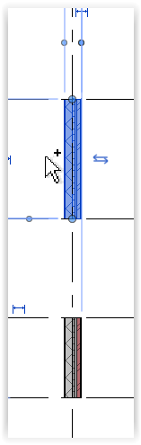
Flip wall orientation
Left-click: wall to be flipped > double arrow to flip the wall > Esc:

Change wall type
Left-click wall to be changed:
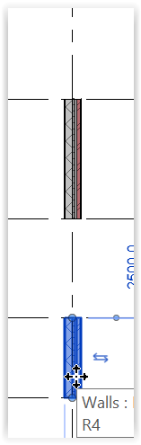
Left-click: Type Selector > Basic Wall - Generic - 200mm:
Esc to finish:
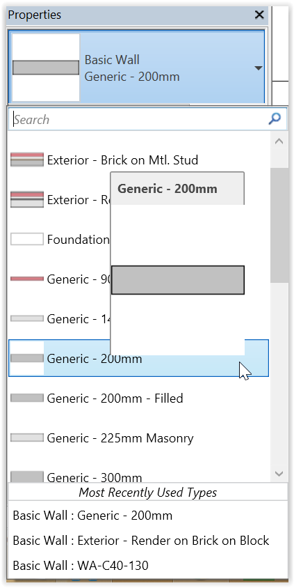
Create wall
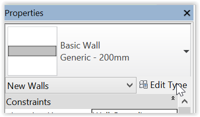
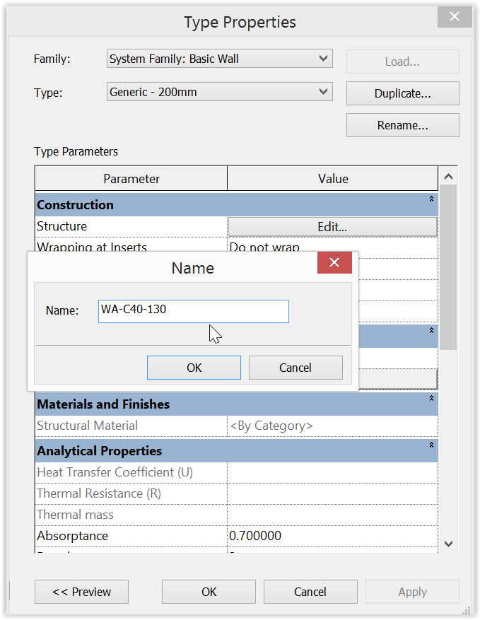
Left-click: Type Selector > Basic Wall - Generic - 200mm > Edit Type:
Left-click Duplicate:
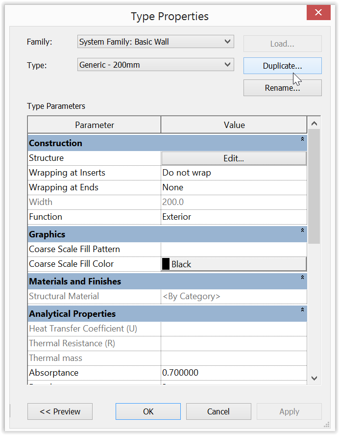
Edit Name:

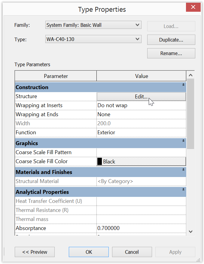
Change to "WA-C40-130" > OK:
where
- WA = Structural wall
- C40 = Reinforcement concrete C40
- 130 = 130 mm thick
Left-click Structure Parameter - Edit:
Edit Thickness:
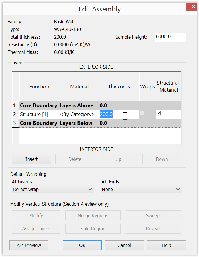
Change thickness to "130.0" > OK:
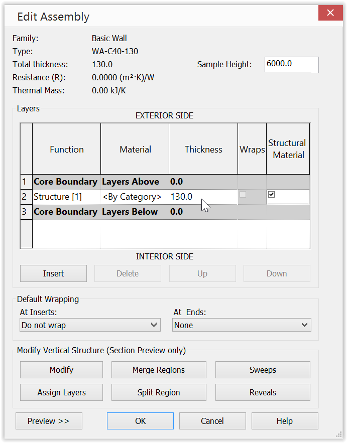
OK:
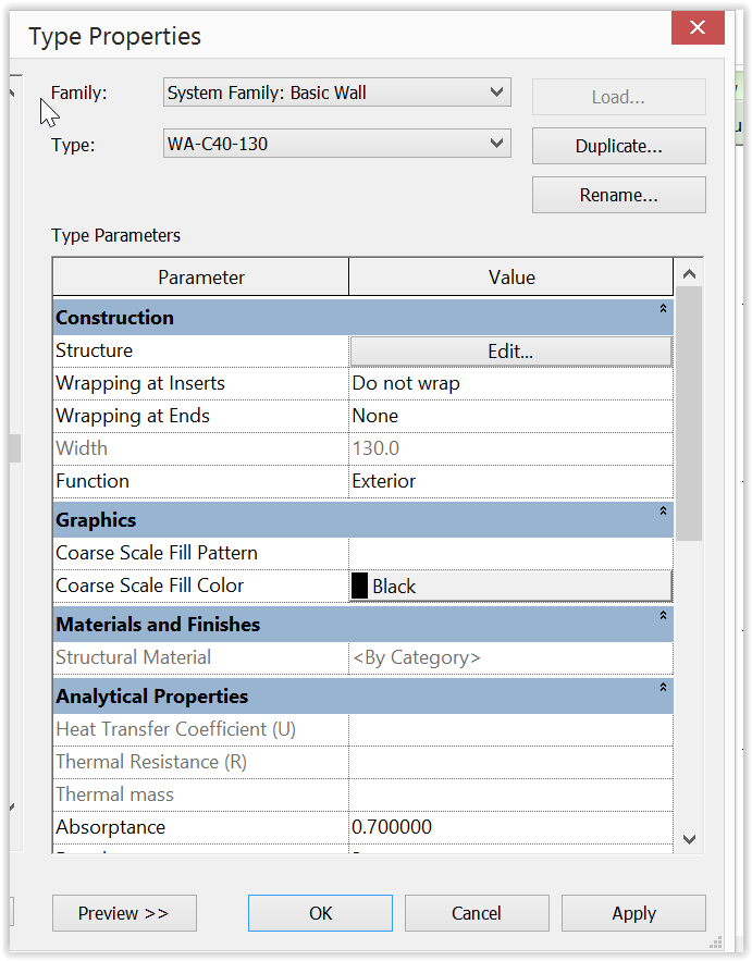
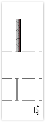
The wall type will be changed:

Join slab to beam
Join slab to beam KCTangNote
5/7/2025: Created with the help of Copilot
Intro
- Join slabs and beams properly in order that the quantities generated from the model are suitable for use.
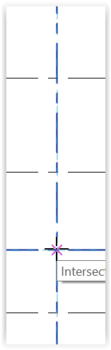
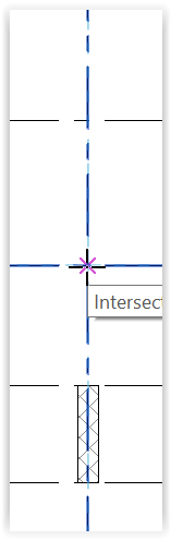
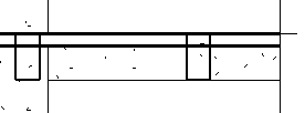
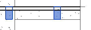
- For HKSMM, slabs should be modelled over beams, i.e. slabs should cut beams in Revit term. This in fact is Revit's default mode.
- Slabs and beams can appear to be joined / overlapped on plans and in sections but are not geometrically joined. Like the following:
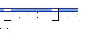
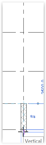
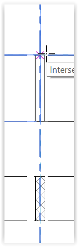
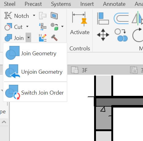
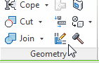
- To switch the join order, select any model element to show the Modify menu.
- Select Join at Geometry panel > Switch Join Order > relevant slab > relevant beam:
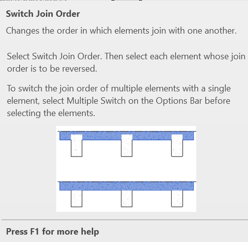
- The switch order can only rectify the problem after modelling.
- Better still, model it correctly in the first instance.
🎯 Why Beam–Slab Joins Go Wrong
Understand how these issues happen and how to catch and correct them.
- Geometry Almost Touches, But Doesn’t: Small misalignments leave elements technically unjoined.
- Sketched by Level, Not Geometry: Slabs snapped to levels or reference planes instead of actual beam faces.
- Copy/Paste Without Rejoining: Duplicated elements don’t retain join data.
- Linework Overrides or Coarse Detail: Visual tools mask missing joins in views.
- Lack of Awareness: Teams may assume visual contact equals geometric join.
✅ Beam–Slab Join QA Checklist
🧱 Geometry Placement
- ✔️ Use beam faces to sketch slabs directly.
- ✔️ Snap slab boundaries to actual beam geometry, not just to levels or reference planes.
- ✔️ Use the Align tool for precision when needed.
- ✔️ Visually check in 3D or section cuts to ensure actual contact.
- ✔️ Don’t rely on 2D guesswork.
🛠 Join Workflow Practices
- ✔️ Model slabs after beams, then join them.
- ✔️ Always use
Join Geometryexplicitly. - ✔️ Rejoin elements after edits to beam/slab placement.
- ✔️ Don’t assume visual contact means joined—confirm using automated tool.
- ✔️ Confirm joins using automated tool.
🧙♂️ Visual Deceptions
- ✔️ Avoid Linework overrides that hide gaps and make unjoined elements appear cleanly cut in views.
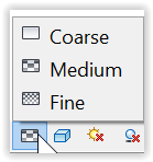
- ✔️ Use Fine detail in review views. Coarse and Medium may mask join gaps.
- ✔️ Run a visual audit by resetting overrides in key views.
🔁 Modeling Efficiency
- ✔️ Rejoin geometry after copy-paste or grouping, Join conditions are not preserved by default when duplicating elements.
- ✔️ Use automated tool to check.
📚 Team Awareness & Training
- ✔️ Train modelers on the purpose and impact of join geometry.
- ✔️ Include checklist in onboarding and BIM standards.
Automated checking tools
- pyRevit scripts have been written to :
- list unjoined slabs and beams,
- join them, and
- switch to slab over beam mode,
- for all beams and slab in close proximity.
- Individual manual adjustments are required for exceptional items.
- Some adjustments cannot be reversed if the model is saved.
- The model should be inspected to see whether the adjustments are correct before saving the model for further use.
Schedule Revit for QTO
Schedule Revit for QTO KCTangNote
2 Mar 2022: Expanded to include previous presentation materials titled "Minimalist Modelling and Coding of Revit for Quantities" presented in February 2014 and January 2015 both in Kuala Lumpur, and on 6 April 2016 in Hong Kong and 2 March 2022 at HKIS.
12 Mar 2015: Created. Titled "Export Revit schedules to Excel.
Intro
One can model BIM to the last bolt and nut and can use third party software to take-off quantities from the BIM model, but this would mean extra work and more license fees.
This article would show how a Revit model and its families of building blocks can be built, coded and scheduled in a minimalist and self-explanatory manner appropriate and sufficient enough for producing auditable dimensions and quantities for costing.
Overview
Capabilities of Revit
Can Revit produce Bills of Quantities from Revit model with the press of a button?
- No.
- It is a modelling software, not a BQ production software.
Can Revit model provide quantities?
- Yes.
- Revit being a building information modelling (“BIM”) software defines its building blocks (“elements”) with parameters which contain a lot of information including quantities of work and materials.
- That’s why BIM is called “parametric modelling”.
Are the quantities in compliance with the standard method of measurement?
- No.
- The SMMs of different countries vary.
Are the quantities provided by a Revit model sufficient and ready enough to be converted to quantities according to the standard method of measurement?
- No.
- Some parameters are not schedulable.
- The lengths, areas and volumes of elements provided by a Revit model may not be the desired lengths, areas and volumes for SMM purposes.
- Concrete shoulders at junctions of different mixes are not available.
- Formwork areas are not available.
- Wall and ceiling finish areas are not readily available.
Then, how can we use Revit model to produce quantities for estimates or BQ?
- There are third party quantity take-off software which can help extract quantities from a Revit model and provide them for estimates, bills of quantities and other uses.
- However, one would still need to write the descriptions and do some linking between the descriptions and the modelling elements.
- The linking resembles on-screen taking-off.
- Depending on the suitability of the model, the linking process may be quick or tedious.
- For some software, extensive formulae would need to be set-up.
- This is difficult to check individually and is therefore prone to errors.
- The beauty of such QTO software is that once the descriptions and linking are done, any changes to the models can be monitored.
- The downside is one has to invest in the license and training costs.
When descriptions are required to be written and quantities required to be classified according to the SMM, Quantity Surveyors are still required.
Can we still get something useful from Revit models without third party QTO software?
- Yes, it is the purpose of this article to explain.
Should QS build models?
Are Revit models readily available from Architects and Engineers?
- Probably not yet for most of the cases.
- While QTO software can handle 2D CAD drawings, the on-screen taking-off process would be more tedious for 2D CAD drawings.
Without a BIM model, should QS build up models?
- QS has evolved from dimension sheet, cut-and-shuffle, schedule, scale rule, curvimeter, planimeter, Lotus 1-2-3 spreadsheet, Excel worksheet, digitizer, on-screen taking off, etc.
- There is no reason why the QTO must be textural and not graphical.
- Having learned the basic tools, modelling the basic features with Revit is easier than with 2D CAD software.
- It should be within the capability of the average QS to learn, only if he or she has time.
- For the bulk items like structure, fabric and finishes, the time to model and get quantities would be shorter than the time to do manual taking off or on-screen taking off from 2D CAD drawings.
- Even if models are provided by Architects and Engineers, they may not have been modelled in such a way suitable for QTO.
- QS should be able to inspect and understand the models in order to use the models.
- Furthermore, in order not to disturb the integrity of the models provided by the Architects and Engineers, QS would probably need his own set of “QS parameters” and adjust the parameters for his own purposes.
- Therefore, the answer should be "yes".
- QS should build up models in the absence of models or should be able to modify models to suit.
Should QS model every detail?
- No.
- Items like windows, doors, fittings and furniture vary in details between different projects and take some longer time to model.
- All that QS needs is the number for writing up full descriptions or measuring the component quantities per number with reference to the detailed drawings provided by the Architects and Engineers.
- It should however be noted that the level of details of the models if provided by the Architects and Engineers should be no less than those traditionally provided for 2D CAD drawings for estimating, tendering and construction. This should be a simpler benchmark than whatever Level of Development or Level of Details (LOD) or Level of Information Need definitions.
How much do we need to measure?
We may measure every bit of concrete, formwork, finishes, etc. exactly net when we measure the concrete members or room finishes.
However, see the following table for the inter-relationship between dimensions and quantities:
|
Description |
Primary Qty |
Multiplier |
Unit |
|---|---|---|---|
|
Wall - grade C40 - T thick (centre line area) |
A |
|
Super |
|
A |
T |
Cube |
|
A |
2 |
Super |
|
|
|
|
|
|
|
|
|
|
|
|
|
Column - grade C40 - W wide x D deep (height) |
H |
|
Run |
|
H |
W x D |
Cube |
|
H |
(W + D) x 2 |
Super |
|
|
|
|
|
Suspended beam - grade C30 - W wide x D deep - S slab (length) |
L |
|
Run |
|
L |
W x (D – S) |
Cube |
|
L |
W + (D – S) x 2 |
Super |
|
L |
W x -1 |
Super |
|
|
|
|
|
Suspended slab - grade C30 - S thick (area) |
A |
|
Super |
|
A |
S |
Cube |
|
A |
|
Super |
|
|
|
|
|
|
|
|
|
Room - finishes group A - net plan area |
A |
|
Super |
|
A |
|
Super |
|
A |
|
Super |
|
|
|
|
|
|
|
|
|
|
|
|
|
Room - finishes group A - perimeter including columns - H room height - S skirting height |
L |
|
Run |
|
L |
|
Run |
|
L |
H – S |
Super |
|
|
|
|
|
|
|
|
|
|
|
|
|
Window W1 - W wide x H high opening - T thick concrete wall - Room A |
N |
|
Nr |
|
N |
|
Nr |
|
N |
Detailed dimensions of W1 |
Super |
|
N |
W x H x T x -1 |
Cube |
|
N |
W x H x 2 |
Super |
|
N |
W + H x 2 |
Run |
|
N |
W x H x -1 |
Super |
|
N |
(W + H x 2) x reveal width |
Run |
|
N |
W |
Run |
|
Door D1 - W wide x H high opening - T thick brickwall - Room finishes group A |
N |
|
Nr |
|
N |
|
Nr |
|
N |
W x H x -1 |
Super |
|
N |
W + end laps x 2 |
Run |
|
N |
W |
Run |
|
N |
W x H x -1 |
Super |
|
N |
W x part of T as appropriate |
Run |
|
N |
Detailed dimensions of D1 |
As appropriate |
The above shows that:
- We may measure the:
- aggregate areas of different wall and slab thicknesses,
- aggregate lengths of different column and beam sections,
- aggregate plan areas and girths of rooms of the same finishes first (we may call these “primary quantities”, those without bullets),
- before converting them into concrete, formwork and finishes quantities (we may call these “secondary quantities”, those with bullets).
- We may measure the overall gross quantities first before making detailed adjustments.
- Some adjustments can be made when we measure other elements, e.g.:
- deduct slab formwork using beam quantities,
- adjust for wall openings when using window and door quantities, etc.
- The descriptions can be very short only to the extent of containing sufficient information for the purposes of the multiplier.
It follows that instead of expecting a Revit model to provide the quantity of every BQ item, we can just:
- extract the primary quantities adequately described from the Revit model; and
- use Excel to handle the secondary processing.
The need for modelling to the last bolt and nut is reduced.
Excel in fact is more powerful for setting up complicated formulae, and for sorting and filtering rows.
Coding and why?
To convey the information from Revit to Excel, it would be good if the information is described in a concise, precise and consistent manner.
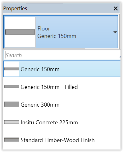
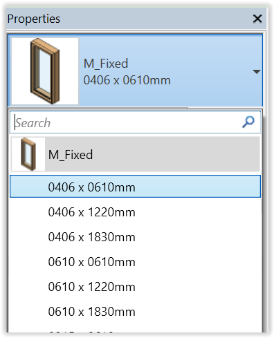
All Revit elements are classified and described by Family (Floor, Basic Wall, M_Fixed in the following images) and Types (those under the Search prompts in the images), but these descriptions may not contain the information the way we want and we would need to change them anyway.
Furthermore, if the model is provided by the Architect or Engineer and we do not want to change their descriptions of Families and Types, we may need to create a parameter to contain the precise and consistent information we need.
The following coding (“QS Desc”) should be sufficient and self-explanatory enough yet short and simple to represent the primary quantities in the above table:
- WA-C40-100
- CL-C40-500x600
- BM-C30-300500 : 120SL
- SL-C30-120
- RM-F-A
- RM-P-A
- WD-W1-1200x1500 : IWConc100-RoomA
- DR-D1-920x2200 : IWBrick125-RoomA
This way of coding should be more intuitive and understandable than those cryptic codes using (alpha) numeric codes.
CIC BIM Standards promote the use of FLIP as the element names. It is not that suitable for QS use. Conversion from FLIP to "QS Desc" would be necessary.
It should be easier to do the conversion in bulk with Excel than with Revit schedules.
Schedules / Quantities
Revit schedules
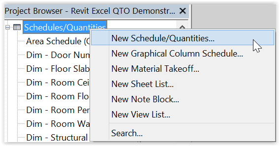
Revit has the capabilities to produce many schedules, under the project browser:
With so many schedules to represent a modelled project, the choices of the columns in the schedules must be well co-ordinated.
We cannot practically transfer the individual total quantity from the schedules manually one by one for billing purposes.
This would be prone to errors.
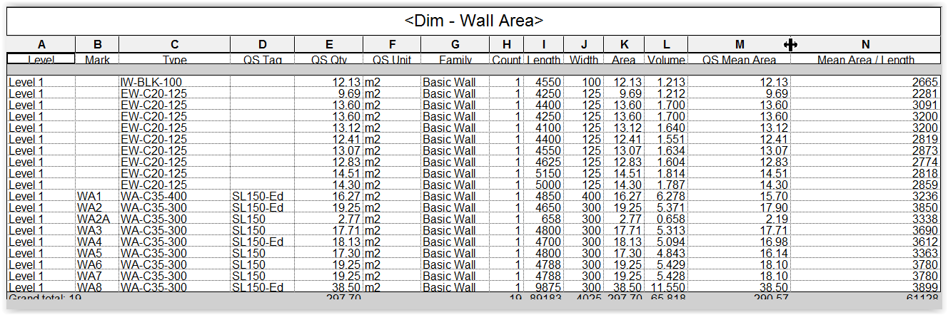
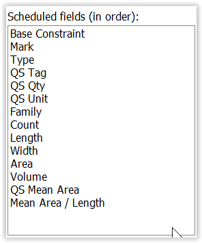
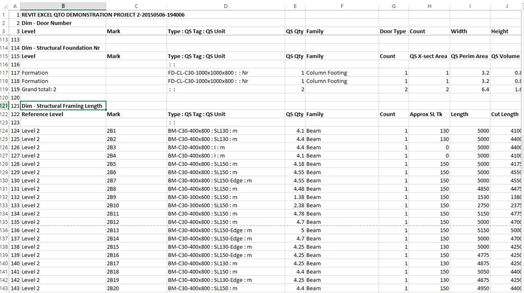
The above schedule has been designed such that:
- The left 6 columns are consistently designed for all schedules.
- The Level and Mark are for locational identification of the quantities, like our dimension sheets, for traceability.
- Only the Type, QS Tag, QS Qty and QS Unit are really essential for billing.
- The other columns are there for calculating the QS Qty or cross-checking, and can vary from schedules to schedules.
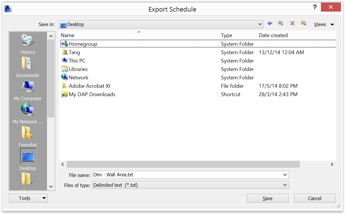
Export function provided by Revit
Revit can also export the schedules to a txt file which can then be imported by Excel to become a worksheet for use:
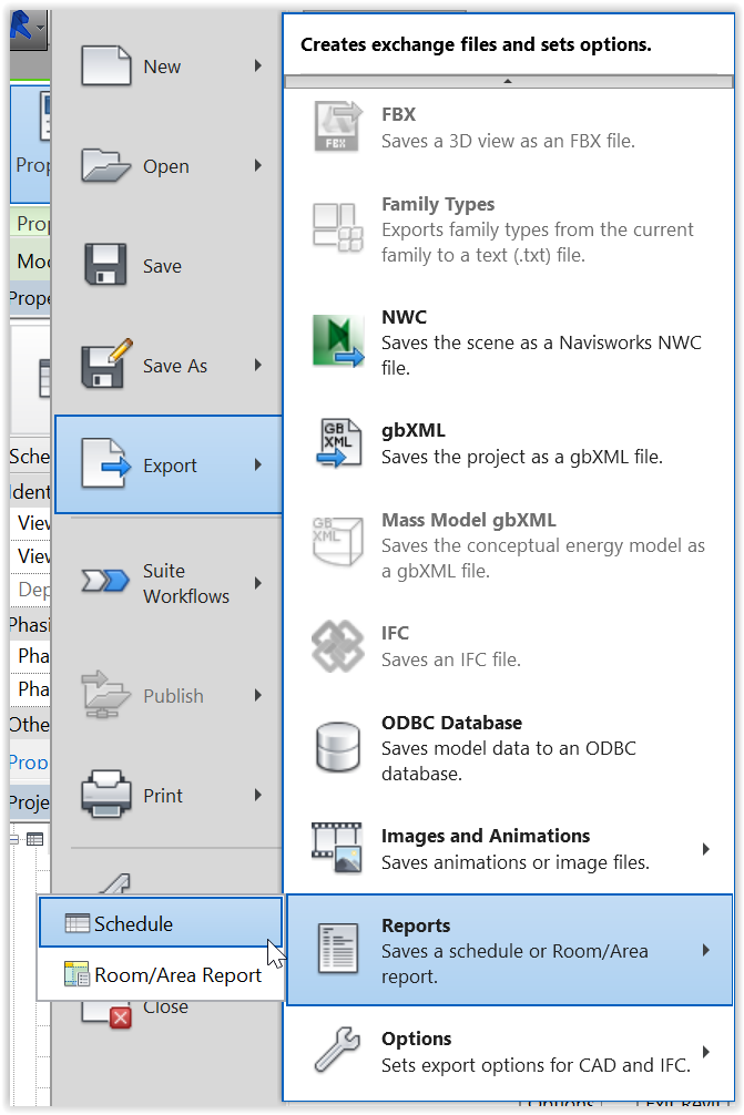
However, the export can only handle one schedule at a time.
This would be a tedious process to export many schedules one at a time and merge all schedules together.
Use macro to export to Excel
A macro (see later below) has been written whereby:
- All the schedules will be exported by a single command to one Excel file with one worksheet per schedule.
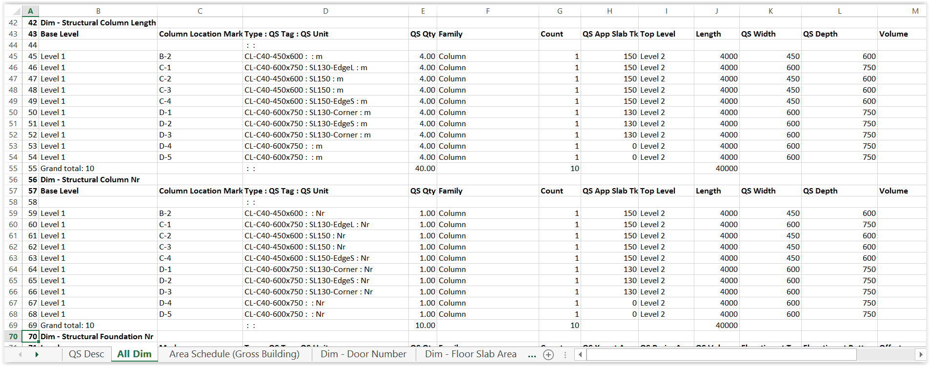
- Schedules intended to provide the uniform left 6 columns for billing should have their names prefixed by “Dim – ” and the macro will combine the 3 columns of Type, QS Tag and QS Unit into a single “QS Desc” column in the style of “Type : QS Tag : QS Unit”.
- An “All Dim” worksheet will be created to repeat all information contained in the “Dim – ” schedules:
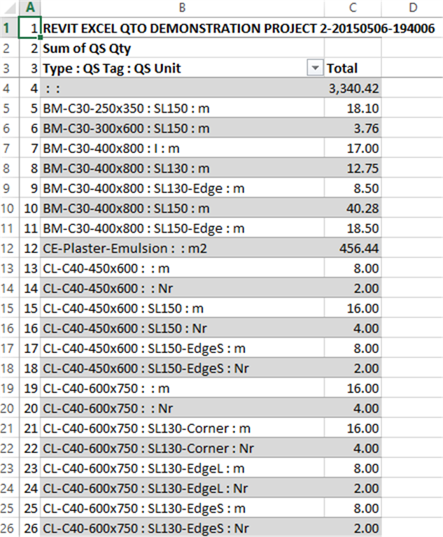
- A “QS Desc” worksheet will be created to contain a list of the unique QS Desc and their total QS Qty:
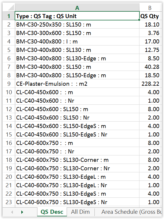
- The total QS Qty will be useful for quick reference.
- The Excel file name will contain the time down to the second it is created so that a re-export will not overwrite an existing Excel file.
This macro vastly reduces the time to export Revit schedules to Excel worksheets.
Billing Workflow
Overall
The primary quantities in the “All Dim” worksheet can be further processed for billing. The workflow are as follows:
- Data --> (extraction from Revit schedules) --> Primary Qty --> (processing ) --> Secondary Qty --> (processing ) --> Estimate or BQ.
- Data --> (direct measurement without using Revit) --> Primary Qty --> (processing ) --> Secondary Qty --> (processing ) --> Estimate or BQ.
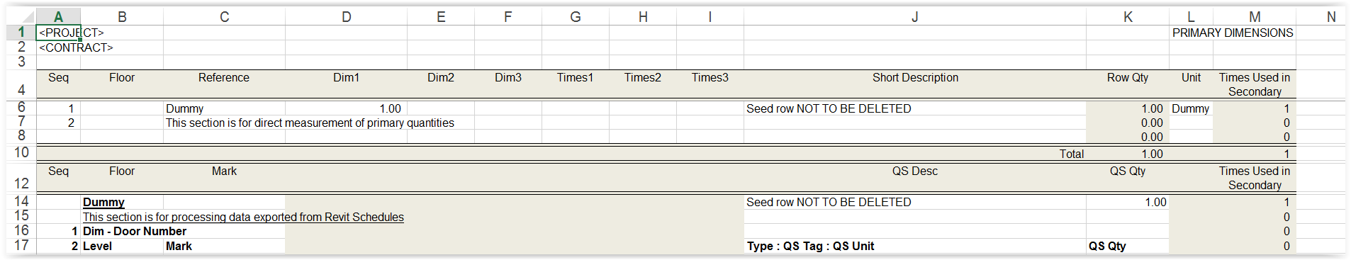
Primary worksheet
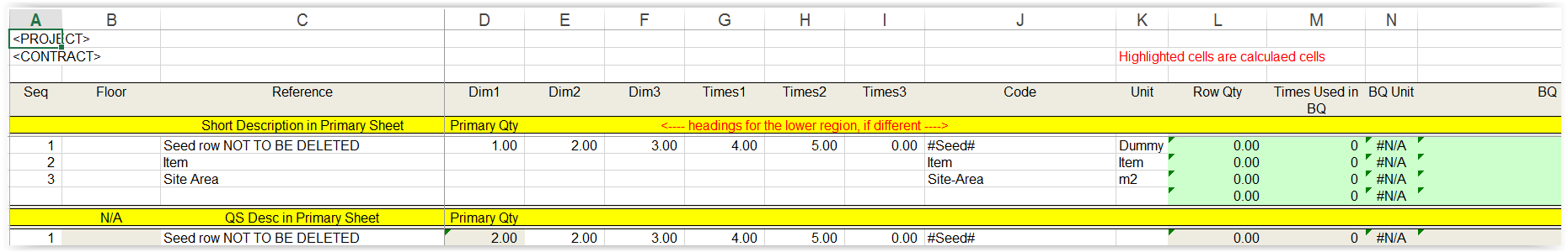
The first 5 columns only of the “All Dim” worksheet shown above are copied to the lower region of a “Primary worksheet”:
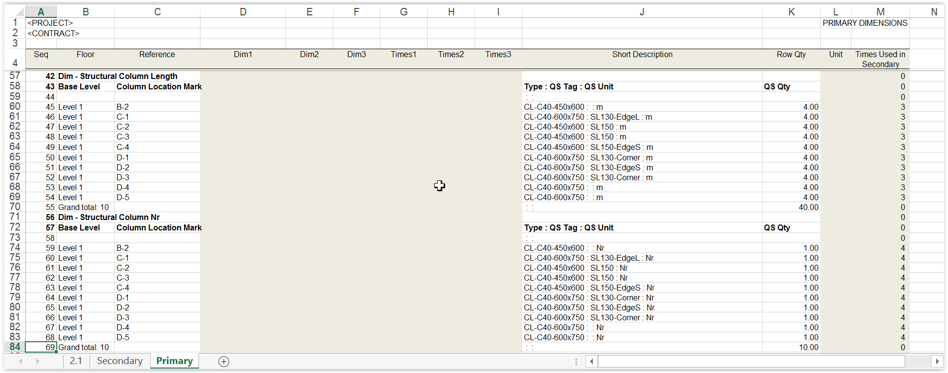
The item sequence can be kept unchanged for easy referencing, or may be sorted temporarily.
The Seq column helps re-sort them back to the original sequence.
Highlighted columns are not used for data exported from Revit Schedules because they are reserved for direct measurement at the upper region of the worksheet, where the formula used for Row Qty, say at Row 6, is =PRODUCT(E6:J6), meaning product of Dim1 …. Times3:
Secondary worksheet
Column A only of the “QS Desc” worksheet shown above is copied to Column B in the lower region of a “Secondary worksheet”:

right portion:
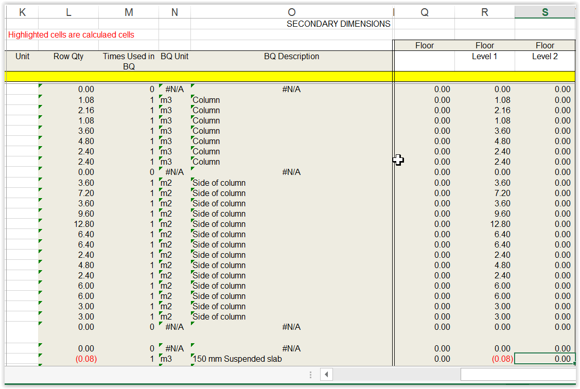
The upper region of the Secondary worksheet is similar to the upper region of the Primary worksheet for direct measurement which can straightly go to the Estimate or BQ without further processing like the lower region:
`
Further processing of the Primary Qty is done in the lower region.
By using a special formula in Column D in the lower region, each of the Primary Qty here is the total of the Primary Qty of the same QS Desc in the Primary worksheet.
There is no need to sort and group the lines in the Primary worksheet in order to give group total per each QS Desc.
The special formula is actually very simple.
For example,
- The Primary Qty at Row 14 is: =SUMIF(Primary!$J$5:$J$181;$C14;Primary!$K$5:$K$181)
- where $C14 is the QS Desc on the same row,
- Primary!$K$5:$K$181 is the range of QS Desc in the Primary worksheet, and
- Primary!$J$5:$J$181 is the range of Row Qty in the Primary worksheet.
- If the QS Desc in the Primary worksheet matches the QS Desc in the Secondary worksheet,
- then add in the corresponding Row Qty in the Primary worksheet.
The Code will be the code of the Estimate or BQ items.
Again, the Row Qty is the product of all Dims and Times of the same row, using the “=PRODUCT()” function.
They are also called Secondary Qty.
The columns like Times Used in BQ, BQ Unit, BQ Descriptions are making reference to the Estimate or BQ worksheet for error checking.
The Floor columns are for analysis of quantities by floors.
Estimate or BQ worksheet
The Estimate or BQ worksheet is like this:
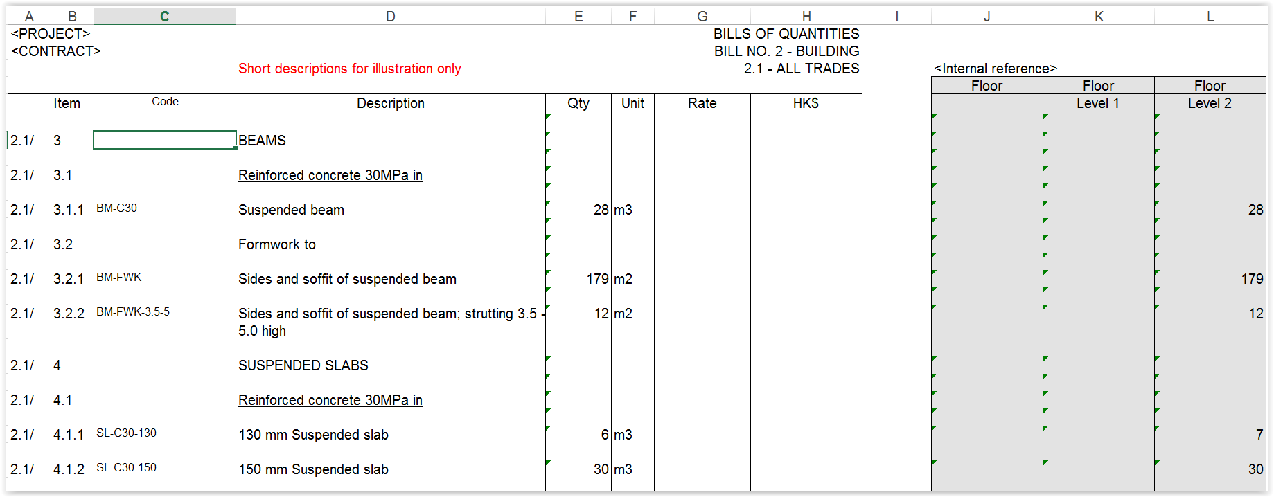
Similar to the Primary Qty or the Secondary worksheet, by using a special formula, each of the Qty here is the total of the Secondary Qty of the same Code in the Secondary worksheet.
The special formula is in the form of:
- =ROUND(SUMIF(Secondary!$J$6:$J$176;$C41;Secondary!$L$6:$L$176);0)
Basically, it means that if the Code in the Secondary worksheet matches the Code in the Estimate or BQ worksheet, then add in the corresponding Row Qty in the Secondary worksheet.
The Floor columns are for internal references only.
When issuing the Estimate or BQ in Excel softcopy, the formulae should be changed to values and other internal reference data should be removed with the empty columns hidden.
Setting Revit Schedules
Project units
Revit schedules show the units against numerical values by default.
It would not be convenient if the numerical values are exported to Excel worksheet for further calculations because they would not be recognised as numerical values unless the units are removed
A solution would be to define two decimal places for Area and three decimal places for Volume with the units hidden, so as to make them self-explanatory without the need of units.
To define the project units (in metric): click Manage > Project Unit icon:
Parameters
Parameters provided by Revit are called system parameters, which cannot be changed though some permit entry of values.
There are two types of parameters which one can define at the Family, Type or Instance level:
- Project Parameters: can appear in schedules but not in tags, but cannot be shared by other projects and families.
- Shared Parameters: can appear in schedules and tags, shared by multiple projects and families, and exported to ODBC.
Shared Parameters are more versatile and useful.
For some Families and Types, a shared parameter can be added to the properties directly.
However, for others, only project parameters can be added to the properties, but a project parameter can borrow a shared parameter, so the shared parameter can still be used but indirectly.
Project parameters
To add project parameters: select Manage > Settings > Project Parameters:
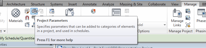
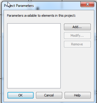
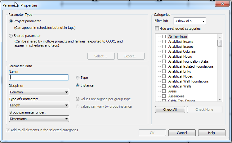
Note from the above that either a project parameter or a shared parameter can be added.
Shared parameters
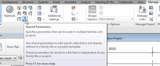
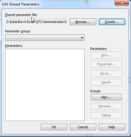
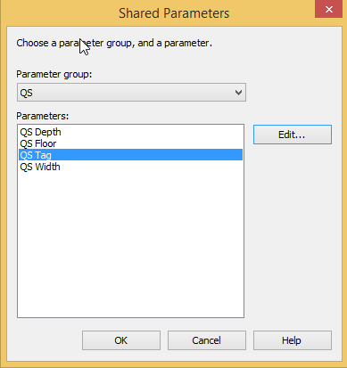
To add shared parameters: select Manage > Settings > Shared Parameters:
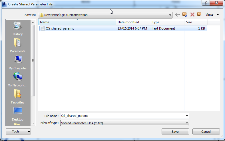
Select Create, go to a convenient folder, name a Shared Parameter file, e.g. "QS_shared_params", which is a txt file, save and return back to the screen on the left:
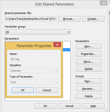
Select New under Group, name a New Parameter Group, e.g. "QS", and select OK.
Select New under Parameters, name a new parameter, e.g. “QS Tag”, select Common under Discipline, select Text under Type of Parameter, and select OK:
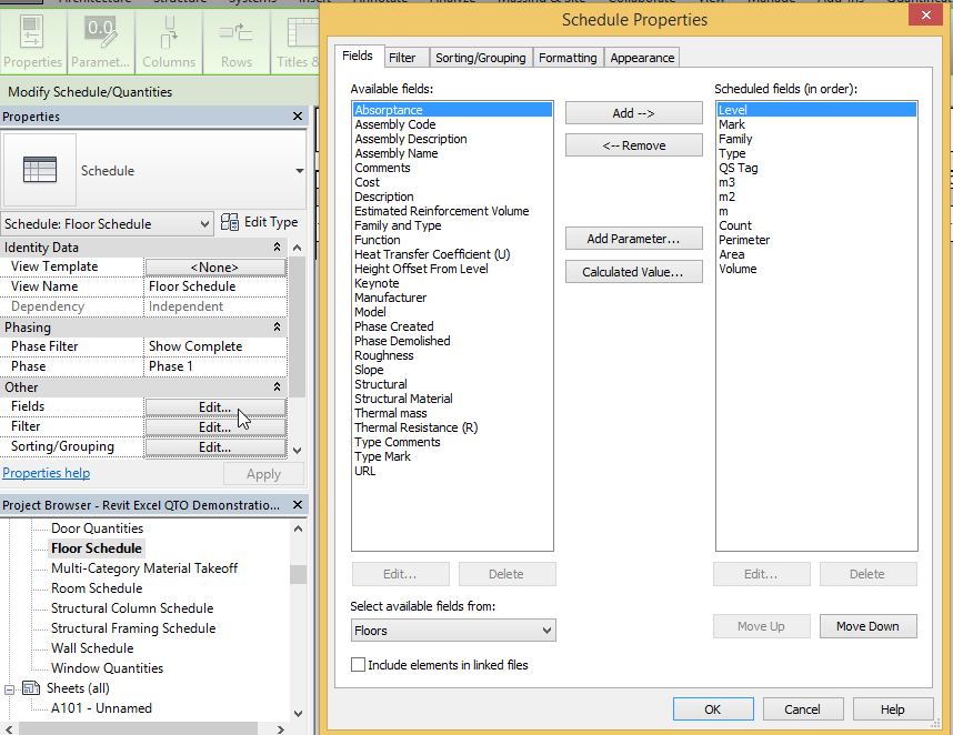
Defining schedule columns
Revit schedule columns (fields) can be selected from “Available fields” (parameters).
If there are no suitable fields available, new columns can be defined either by “Add Parameter” or “Calculated Value”:
Level and Mark
Level and Mark parameters are generally available with elements.
Type
Elements are classified by Family and generally have a Type parameter available for use in the schedules.
However, instead of using Family and Type as provided by Revit, short-code-like-descriptions are used for Type.
To simplify matters, such descriptions should represent both the information of Family and Type.
QS Tag
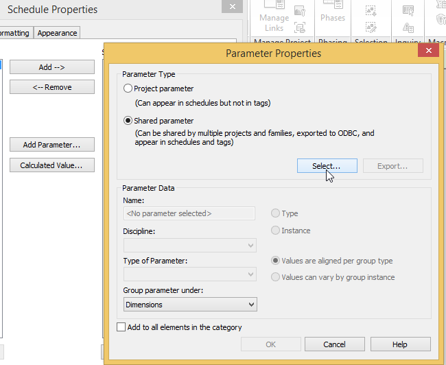
QS Tag is a new parameter specially added to supplement the information of “Type”.
Select Add Parameter as shown above to open the Parameter Properties window.
Select Shared parameter > Select to open another window.
Select the Parameter Group QS if it already exists, otherwise create it as described for Shared Parameters.
Select QS Tag if it already exists, otherwise create it as described for Shared Parameters by selecting Edit.
Select OK to go back to the Parameter Properties window.
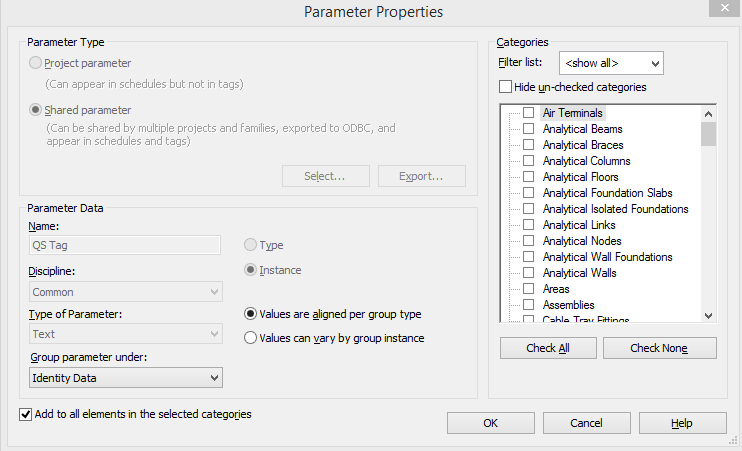
Check “Add to all elements in the selected categories” and Instance.
Select Identity Data under “Group parameter under”, and select OK.
Move up the newly created parameter on the menu to the desired position.
QS Qty and QS Unit
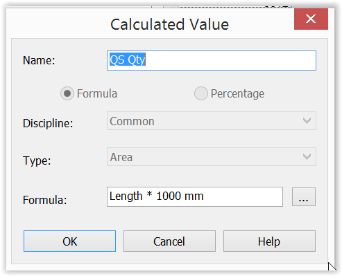
QS Qty is a calculated field borrowing its value from other parameters like Count, Length, Area, Volume, etc.
The unit of QS Qty can be Nr, m, m2, m3, i.e. a mixture.
However, Revit does not permit a column of such mixed nature.
Since QS Qty should have 2 decimal places, therefore, it is artificially defined as an Area parameter which according to the setting of the Project Units described earlier will show 2 decimal places.
However, tricks have to be done as shown below to make their numerical values still correct even though they are recognised by Revit as Area parameters:
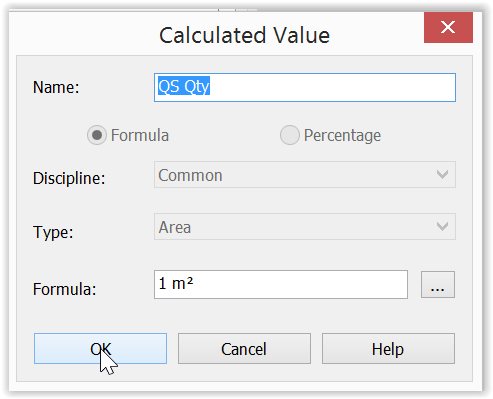
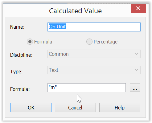
QS Unit is a calculated field specially used to tell the real unit of QS Qty. The formulae are simply “m” for “m”, “m2” for “m2”, “m3” for “m3”, “Nr” for “Nr”, etc.
It may be possible for some elements that we need their Count, Length, Area as QS Qty, e.g. Column Nr and Column Length, Wall Area and Wall Length. To handle this, the same schedule can be duplicated only with the QS Qty and QS Unit suitably adjusted to suit while all other fields can be kept the same.
Example schedules
Wall schedules
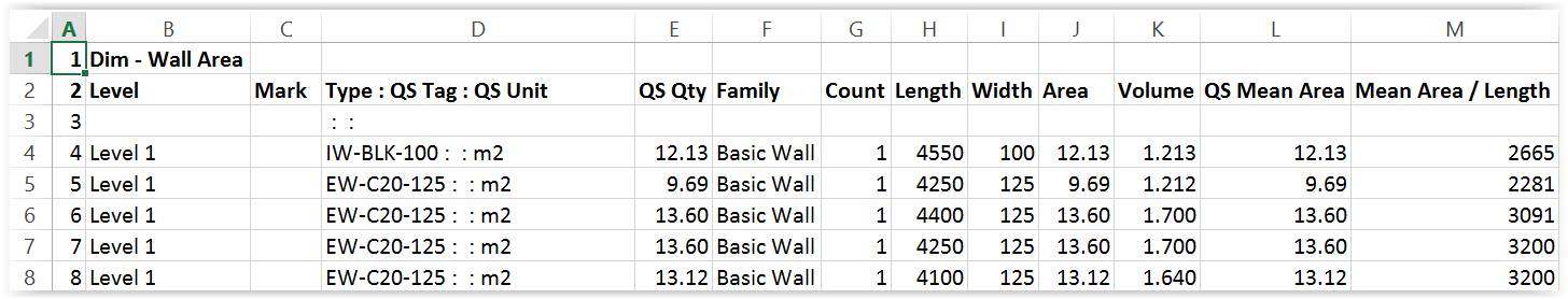
A Wall Area schedule gives wall areas as QS Qty for the generation of concrete volume and formwork area:
A Wall Length schedule gives wall lengths as QS Qty for the processing of quantities at junctions with slabs:
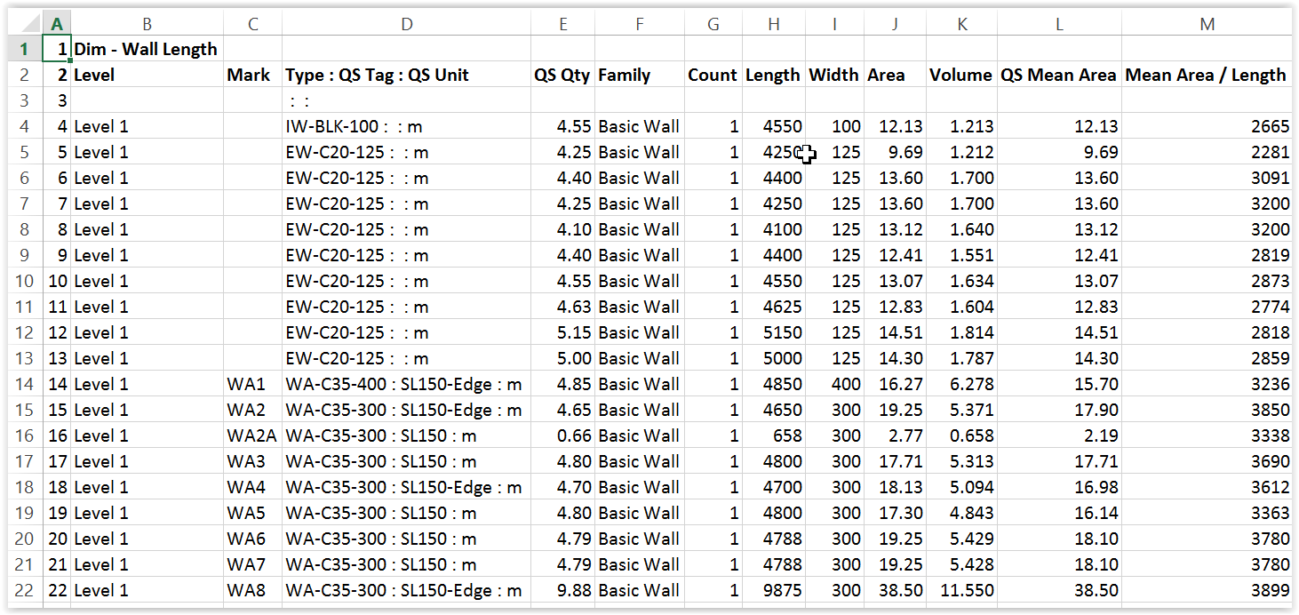
Level is actually the base constraint renamed in the schedule heading. This is not absolutely necessary for billing purposes.

QS Tag is for entering information like the slab thickness and whether the wall is at slab edge to facilitate adjustment for slab and wall junctions.
Length, Width (i.e. thickness), Area and Volume are system parameters.
Note that Area is not always equal to the elevation areas along the centre line as explained later and would need special treatment.
Wall height is not available probably because the height can vary for a wall.
Lengths at wall ends are not available.
This is to be resolved.
Lengths around openings are not available.
This is to be resolved through giving more information on the Door and Window Schedules.
For blank openings, this is still to be resolved.
QS Mean Area is equal to Volume / Width.
“Mean Area / Length” is equal to QS Mean Area / Length.
Representation of wall length, area and volume
Note the wall length, area and volume have the following representations:
|
|
Wall length given |
Area given |
Volume given |
|---|---|---|---|
|
Straight wall e.g. |
Centre line of wall = |
Elevation area on one face = 12 x = |
Area along centre line x wall thickness = 12 x 4 x = |
|
Wall L-shaped on plan with mitre joint e.g. |
Centre line of wall with the corner shared between the two wings = 7.85 + = |
Elevation area based on the extreme length of each wing = 8 x 4 + 5 x = 32 + = |
Area along centre line with the corner shared x wall thickness = 7.85 x 4 x 0.4 + 4.80 x 4 x 0.3 = 12.56 + = |
|
Wall L-shaped on plan with butt joint e.g. |
Same as above |
Elevation area based on the self length of each wing = 8 x 4 + 4.6 x = 32 + = |
Area based on self length x wall thickness = 8 x 4 x 0.4 + 4.6 x 4 x 0.3 = 32 x 0.4 + 18.4 x 0.3 = 12.80 + = |
|
Wall L-shaped on plan with butt joint e.g. |
Same as above |
Elevation area based on the self length of each wing = 7.7 x 4 + 5 x = 30.8 + = |
Area based on self length x wall thickness = 7.7 x 4 x 0.4 + 5 x 4 x 0.3 = 30.8 x 0.4 + 20 x 0.3 = 12.32 + = |
|
Wall T-off from another wall e.g. 4.6 x
|
Centre line of T-off wall measured to centre line of main wall = 4.6 + 0.2 = |
Elevation area based on the self length of T-off wall = 4.6 x = |
Area based on self length x wall thickness = 4.6 x 4 x 0.3 = |
The Area and Volume do not make deduction at the junction with floor slab.
Whether the L-shaped wall is mitre or butt jointed, it does not make any difference to the Volume, but the Areas are different for the three cases.
The area of formwork to sides of wall should be equal to the elevation area along the centre line x height x 2 = (7.85 + 4.8) x 4 x 2 = 50.6 m2 x 2.
The Areas given by Revit for the three cases of L-shaped wall are useless for this purpose.
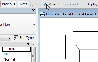
Wall junctions on plan:
- It is preferred to use mitre joints at corner junction of walls.
- To change the type of wall junctions on plan: select a wall > Wall Joins:
- Select Butt to give a butt joint:
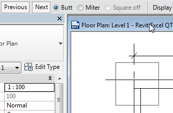
- Select Previous or Next to change the direction of the joint:
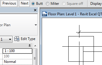
- Select Miter for a mitre joint:
After all these discussions, it seems that Volume is a more reliable value to use than Area.
Therefore, QS Qty using Wall Area for Estimate and BQ purposes takes the value of Volume / Width, i.e. the QS Mean Area.
QS Qty using Wall Length is to be used for adjustments for the wall and slab junction, it appears that Length is not accurate enough but close enough and is the only choice available. It is to be addressed.
Architectural walls
Architectural walls can be modelled just like a structural wall.
However, unlike structural walls which can be taken as going up to the floor level because they usually have stronger concrete grade, architectural walls should go up to beam or ceiling soffit only and not the floor level.
Revit does not have a feature to let architectural walls automatically go up and stop there.
Therefore, architectural walls have to be modelled one by one to ensure correct height.
With so many architectural walls within a building, this is a time consuming process and is therefore prone to errors.
A solution is to model architectural walls like structural walls up to the floor level above, and select the Join > Switch Join function so that the slabs and beams will override the walls so that the wall volumes and areas reported will be those below the slabs or beams.
Floor slab and structural wall junctions
When modelling, after selecting a floor slab >
 >
>  > Yes, the following dialogue will appear and will only appear if there are structural walls underneath the slab:
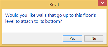
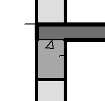
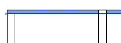
If “Yes” is selected, the volume of the structural walls below will be measured to the underside of the slab, as shown for the wall on the left below.
If “No” is selected, the volume of the structural walls below will be measured to the top of the slab, as shown for the wall on the right below, but the reported volume of the slab will not be reduced.
The reported height of the structural walls when defined to be to the top of the slab will not be changed in both cases.
In theory, when a structural wall is attached to the bottom of a floor slab, the wall top will move when the floor slab is moved up or down.
Furthermore, the Modify Wall menu also has the following choices:
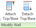
However, the behaviour after attaching or detaching walls using the above slab or wall commands is not quite definite every time.
Furthermore, since the slab and wall junctions will need to be adjusted in any case, when encountering the above dialogue when editing slab boundary, it is better to answer “No” to retain the default treatment.
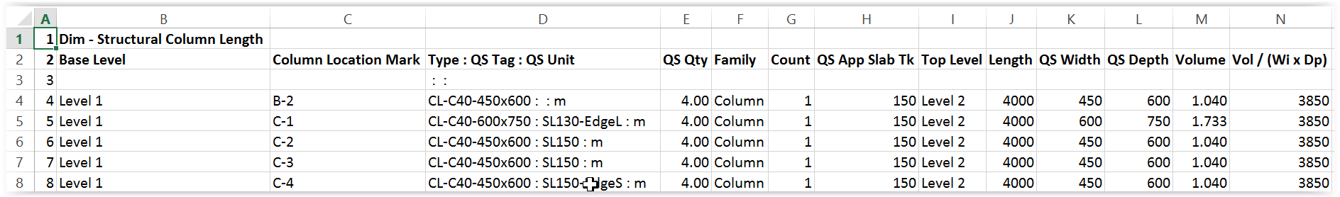
Structural column schedules
A Structural Column Length schedule gives column lengths as QS Qty for the generation of concrete volume and formwork area:
A Structural Column Number schedule gives column numbers as QS Qty for the processing of quantities at junctions with slabs:
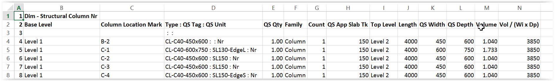
Column Location Mark is a system parameter which gives the grid line references.
This is used here instead of the usual Mark.
QS Tag is for entering information like the slab thickness and whether the column is an edge or corner column to facilitate adjustment for slab and column junctions.
For a column defined to be of floor to floor height, Volume is a system parameter which gives the volume of concrete below slab, while Length is a system parameter which gives the floor to floor height.
Since the floor to floor height is needed, therefore “QS Qty” takes the value of Length for Column Length schedule.
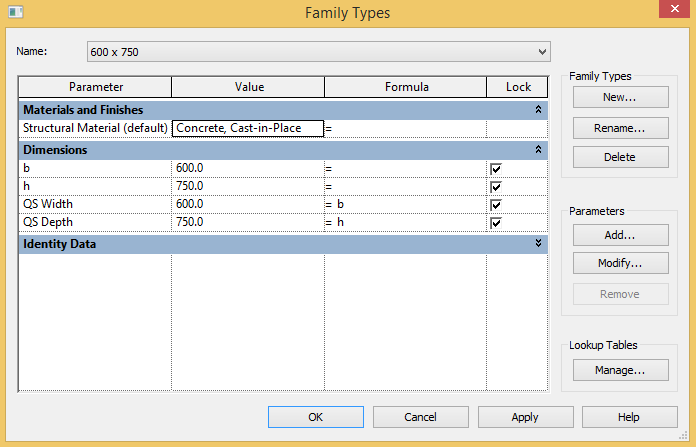
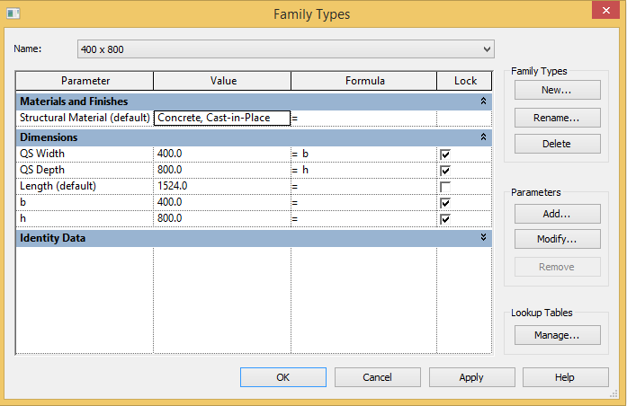
It is strange that the column width (b) and depth (h) are not available to the properties window and schedules.
Therefore, two shared parameters QS Width and QS Depth have been added to the Family Type parameters to make them available to the schedules to facilitate error checking.
QS App Slab Tk = Length - Volume / (QS Width * QS Depth) which is useful for indicating the approximate slab thickness for counter-checking any errors in positioning the columns.
Vol / (Wi x Dp) = Volume / (QS Width * QS Depth) gives the length of column below slab.
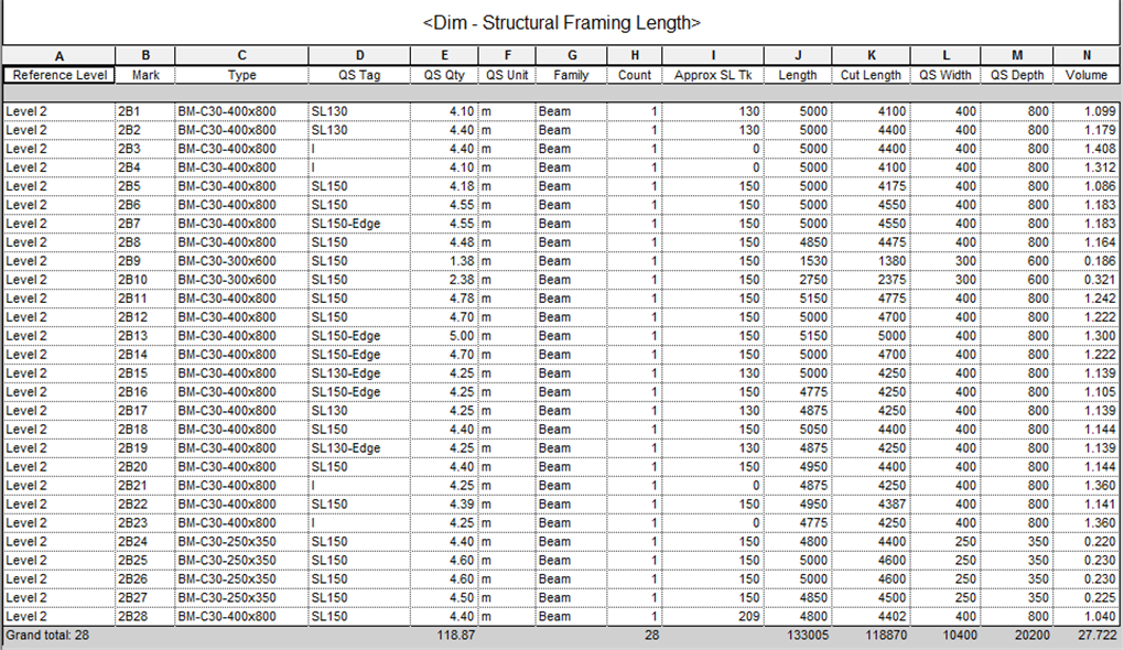
Structural framing length schedule
Structural Framing Length schedule is basically a beam length schedule:
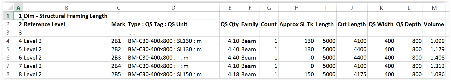
For beams, there are two parameters of Length and Cut Length.
Only the Cut Length is the length between supporting columns or walls.
QS Qty for Beam Length takes the value of Cut Length.
Similar to structural columns, the beam width (b) and depth (h) are not available to the properties window and schedules.
Therefore, two shared parameters QS Width and QS Depth have been added to the Family Type parameters to make them available to the schedules to facilitate error checking:
Floor slab area schedule
A Floor Slab Area schedule can be:
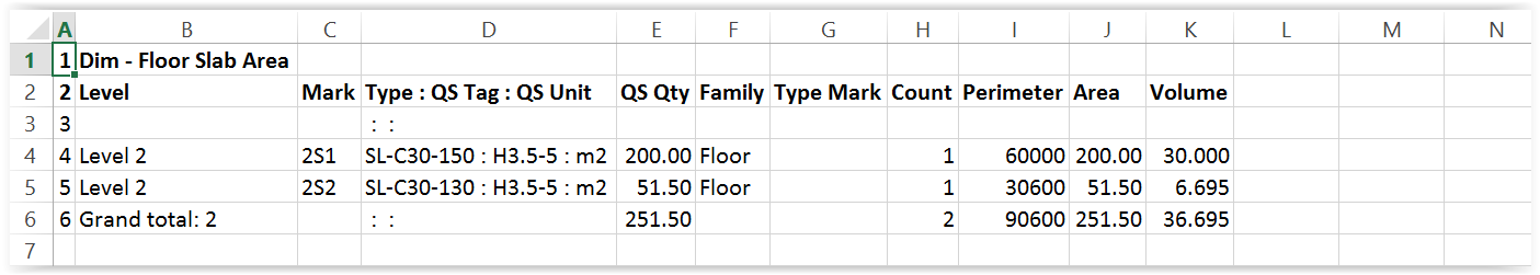
QS Tag is for the entry of information about the strutting height.
QS Qty takes Area.
Door and window schedules
A Door Number schedule can be:
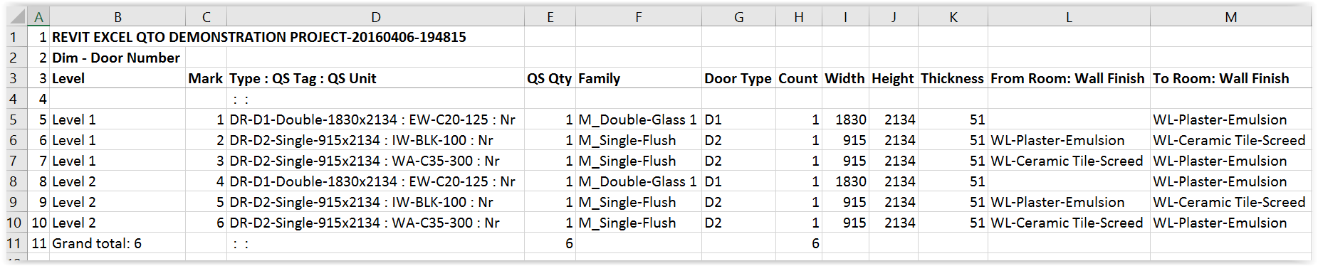
The values of “From Room : Wall Finish” and “To Room : Wall Finish” are obtained with the help of a self-written macro to facilitate adjustment of wall finishes on both sides of the windows.
A Window Number schedule can be:
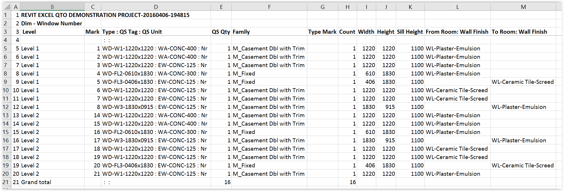
QS Tag is for the entry of information about the walls housing the doors and windows to facilitate future measurement of formwork to jambs and soffit, boxing and lintels.
Room schedules
The default room schedules provided by Revit can give Floor Area and Perimeter, but not the Nett Ceiling and Beam surface areas, nor wall and column surface areas:
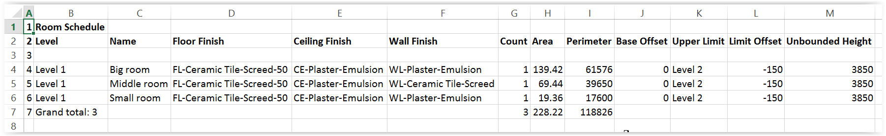
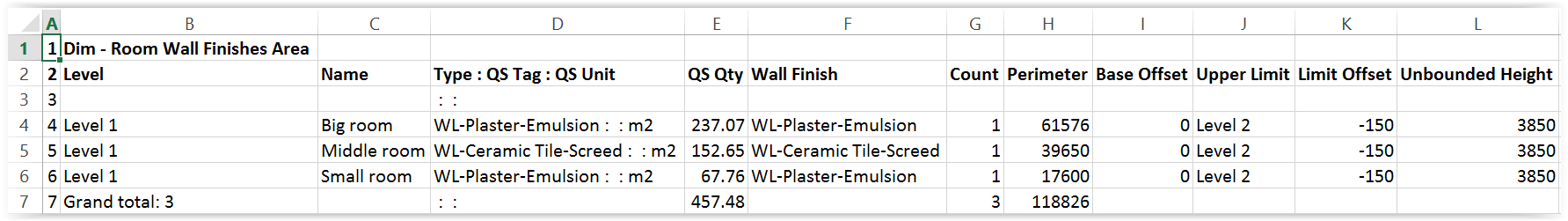
By defining the floor level above a room as the Upper Limit, and entering the slab thickness in negative value as the Limit Offset, the reported Unbounded Height will give the floor to ceiling soffit height, which should be good for generating the wall and column surface areas.
Adjustment would need to be made for the beam surfaces and end junctions.
Adjustment for window and door openings may be taken care of when processing the window and door quantities.
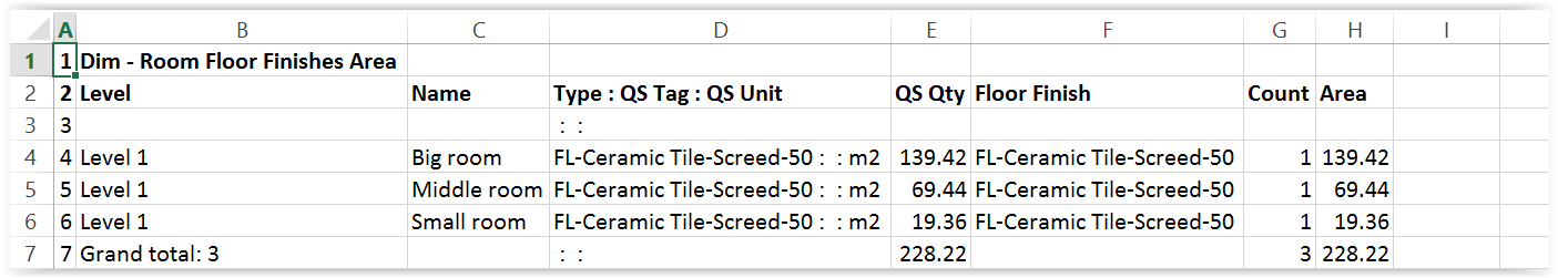
To provide QS Qty for floor, wall, ceiling and skirting, 4 separate schedules are adapted from the Room Schedule.
Room Floor Finishes Area schedule:
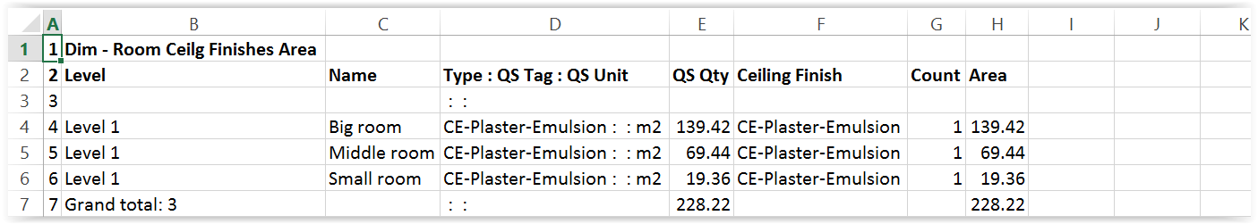
Room Ceiling Finishes Area schedule:
Room Wall Finishes Area schedule, with skirting area to be deducted from wall area:
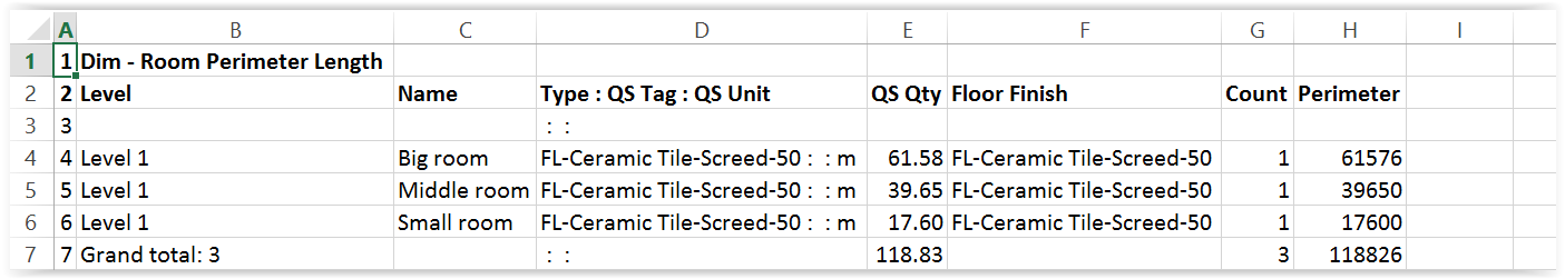
Room Perimeter Length schedule, for skirting:
Room elements do not have a Type parameter.
A calculated field has been created for Type, which takes the names of the finishes as its values.
Conclude
Having set up the Revit schedules and the corresponding Excel worksheets once, they can be re-used as a set of templates for other Revit models.
The number of chains of QS Desc --> secondary calculations --> Codes can be expanded as and when they are encountered and retained in the templates to serve future use to reduce the burden of re-defining every time.
Get into modelling which is easy and powerful as soon as possible.
Understand it, identify the limitations and suggest solutions to make it really productive.
Macro
A Macro to Export all Revit Schedules to a Single Excel File in One Go is given below.
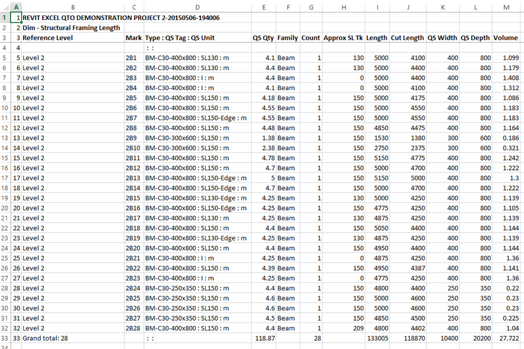
Original Revit View Schedule
Exported to Excel Worksheet
with columns "Type", "QS Tag" and "QS Unit" combined as column D followed by column "QS Qty" as column E:
"All Dim" Worksheet
containing contents of all worksheets beginning with "Dim - ":
"QS Desc" Worksheet
containing all unique descriptions of "Type : QS Tag : QS Unit" with total "QS Qty"
Codes
Revit Macro KCTCL (20150524a).txt
/* Export All Revit Schedules to One Excel file
* Written by: K C Tang
* Using: SharpDevelop.
*
* Date last revised: 24/5/2015
* Revision notes: Handle errors when there are no "Dim - " schedules to
*    fill the "All Dim" worksheet to serve as the source of
*    the pivot table on the "QS Desc" worksheet.
*    Handle errors when the folder is read only,
*    such as a folder of the sample projects provided by Revit.
* Revision notes on 6/5/2015:
*    Speed drastically increased (reduced to 1/4) by using Excel functions
*    as much as possible instead of manipulating Excel file cell by cell.
*    Pivot table used for "QS Desc" worksheet.
*    Sheet header added.
*    Frozen panes set.
*    Page setup set.
* Revision notes on 19/1/2015:
*    Bug fixing and general improvements.
* Date first released for use : 31/12/2014
*    Notes: Export all Revit view schedules to one Excel file.
*    Schedules with names beginning with "Dim - " will have:
*    - columns "Type", "QS Tag" and "QS Unit" combined into one column;
*    - column "QS Qty" moved to next to the combined column;
*    - an "All Dim" worksheet created to contain all these schedules; and
*    - a "QS Desc" worksheet created to contain unique list of "Type : QS Tag : QS Unit".
*
*/
// using libraries
using System;
using System.Collections;
using System.Collections.Generic;
using System.Linq;
using Autodesk.Revit.DB;
using Autodesk.Revit.DB.Architecture;
using Autodesk.Revit.UI;
using Autodesk.Revit.UI.Selection;
using Excel = Microsoft.Office.Interop.Excel;
/* Microsoft.Office.Interop.Excel must be added separately
* by selecting SharpDevelop's menu: Project > Add References,
* and searching for it, then selecting it.
*/
namespace KCTCL
{
  [Autodesk.Revit.Attributes.Transaction(Autodesk.Revit.Attributes.TransactionMode.Manual)]
  [Autodesk.Revit.DB.Macros.AddInId("E77FD3DE-05E8-4FD3-B85A-116F5B6F2EEF")]
  public partial class ThisApplication
  {
    private void Module_Startup(object sender, EventArgs e)
    {
    }
    private void Module_Shutdown(object sender, EventArgs e)
    {
    }
    #region Revit Macros generated code
    private void InternalStartup()
    {
      this.Startup += new System.EventHandler(Module_Startup);
      this.Shutdown += new System.EventHandler(Module_Shutdown);
    }
    #endregion
    public void ExportAllSchedulesToOneExcel()
    {
      // all data names must be intialized first and have their types declared with type names before them
      // define row number to insert column header
      const int col_header_row = 3; // const int = integer constant type
      // keep the starting time
      DateTime time_start = DateTime.Now; // Datetime = datetime type
      // select active Revit document
      Document doc = this.ActiveUIDocument.Document; // Document = document type
      // get filename from doc.Title
      string filename_no_ext = doc.Title; // string = string type
      // add ".rvt" temporarily to doc.Title not ending with ".rvt"
      // because file explorer may have been set to hide the extension
      if (!filename_no_ext.EndsWith(".rvt")) // ! = not
      {
        filename_no_ext = filename_no_ext + ".rvt"; // + = join text together
      }
      // get active folder name by removing the full file name
      // from the full pathname which contains the full file name
      string folder_name = doc.PathName.Replace(filename_no_ext, ""); // replace filename with nothing
      // change file extension to the current datetime string
      // to avoid overwriting existing files
      filename_no_ext = filename_no_ext.Replace(".rvt",
        DateTime.Now.ToString("-yyyyMMdd-HHmmss")); // line considered complete only if ending with ";"
      // initilize Excel variables
      Excel.Application xlApp;
      Excel.Workbook xlWorkBook;
      Excel.Worksheet xlWorkSheet;
      Excel.Worksheet xlWorkSheetAllDim;
      Excel.Range xlRange;
      Excel.Range xlRange2;
      Excel.QueryTable xlQuery;
      xlApp = new Excel.Application();
      // check whether Excel is installed
      if (xlApp == null)
      {
        TaskDialog.Show("ExportAllSchedulesToOneExcel", "Excel is not installed!!");
        return;
      }
      // define an object to represent default value
      object default_value = System.Reflection.Missing.Value; // object = object type
      // create new workbook, which by default contains at least 1 worksheet
      xlWorkBook = xlApp.Workbooks.Add(default_value);
      // initialize 2 worksheet variables, all referring to Sheet1 for the time being
      xlWorkSheetAllDim = (Excel.Worksheet)xlWorkBook.Worksheets.get_Item(1);
      xlWorkSheet = (Excel.Worksheet)xlWorkBook.Worksheets.get_Item(1);
      // rename Sheet1 to contain contents of all future worksheets
      // with names starting with "Dim - "
      xlWorkSheetAllDim.Name = "All Dim";
      // maximize workbook window
      xlApp.ActiveWindow.WindowState = Excel.XlWindowState.xlMaximized;
      // show menu bars
      xlApp.Visible = true;
      // read viewschedules in Revit active document
      ViewScheduleExportOptions opt = new ViewScheduleExportOptions();
      FilteredElementCollector collector = new FilteredElementCollector(doc).OfClass(typeof(ViewSchedule));
      if (collector.ToElementIds().Count == 0) // == means compare for equality
      {
        TaskDialog.Show("ExportAllSchedulesToOneExcel", "No schedule available!!");
        // close workbook without saving
        xlWorkBook.Close(false, default_value, default_value);
        xlApp.Quit();
        // release objects
        releaseObject(xlWorkSheet);
        releaseObject(xlWorkSheetAllDim);
        releaseObject(xlWorkBook);
        releaseObject(xlApp);
        return;
      }
      // sort elements in collector in ascending order
      IOrderedEnumerable< ViewSchedule > sorted_collector =
        from ViewSchedule view_schedule in collector orderby view_schedule.Name ascending select view_schedule;
      // process schedule in ascending order
      int all_dim_new_row = 0;
      foreach (ViewSchedule view_schedule in sorted_collector)
      {
        // check if schedule name too long
        if (view_schedule.Name.Length > 31 )
        {
          TaskDialog.Show("ExportAllSchedulesToOneExcel",
            view_schedule.Name + "\n" + "Schedule name should not be more than 31 characters!!");
          // release objects
          releaseObject(xlWorkSheet);
          releaseObject(xlWorkSheetAllDim);
          releaseObject(xlWorkBook);
          releaseObject(xlApp);
          return;
        }
      }
      foreach (ViewSchedule view_schedule in sorted_collector)
      {
        if (view_schedule.Name.StartsWith("<"))
        {
           // skip schedule with name beginning with "<", such as "<Revision Schedule>"
        } else
        {
          // reduce filename length longer than 31
          if (31 < view_schedule.Name.Length )
          {
            view_schedule.Name = view_schedule.Name.Substring(0, 14) + " name length > 31";
          }
          // replace special character with "_"
          view_schedule.Name = view_schedule.Name
            .Replace( ':', '_' )
            .Replace( '*', '_' )
            .Replace( '?', '_' )
            .Replace( '/', '_' )
            .Replace( '\\', '_' )
            .Replace( '[', '_' )
            .Replace( ']', '_' );
          // export schedule to txt file
          try {
            view_schedule.Export(folder_name, filename_no_ext + ".txt", opt);
          } catch (Exception) {
            TaskDialog.Show("Exporting view schedules",
                            "Errors occurred -\n" +
                            "possibly the folder is read only\n" +
                            "e.g. in the case of sample projects provided by Revit,\n" +
                            "save the project to another folder first.\n\n" +
                            "Close to exit program.");
            // release objects
            releaseObject(xlWorkSheet);
            releaseObject(xlWorkSheetAllDim);
            releaseObject(xlWorkBook);
            releaseObject(xlApp);
            return;
          }
          // add a worksheet
          xlWorkSheet = (Excel.Worksheet)xlWorkBook.Worksheets.Add(default_value);
          // move it to become the last worksheet
          xlWorkSheet.Move(default_value, xlWorkBook.Worksheets[xlWorkBook.Worksheets.Count]);
          // name worksheet as schedule name
          xlWorkSheet.Name = view_schedule.Name;
          // import txt file into worksheet starting at cell at column A, one row above col_header_row
          xlQuery = xlWorkSheet.QueryTables.Add(
            "TEXT;" + folder_name + filename_no_ext + ".txt",
            xlWorkSheet.get_Range("A" + (col_header_row - 1)));
          xlQuery.RefreshStyle = Excel.XlCellInsertionMode.xlInsertEntireRows;
          xlQuery.Refresh(false); // false means refresh but not return until refresh is finished
          xlQuery.Delete(); // delete the query
          // input into All Dim worksheet for schedules with names starting with "Dim - "
          if (view_schedule.Name.StartsWith("Dim - "))
          {
            // insert blank new column A
            xlWorkSheet.get_Range("A1").EntireColumn.Insert();
            // find Type, QS Tag and QS Unit columns
            int col_Type = 0;
            int col_QS_Tag = 0;
            int col_QS_Unit = 0;
            int col_QS_Qty = 0;
            col_Type = xlColumnFindExact(xlWorkSheet, "Type", col_header_row);
            col_QS_Tag = xlColumnFindExact(xlWorkSheet, "QS Tag", col_header_row);
            col_QS_Unit = xlColumnFindExact(xlWorkSheet, "QS Unit", col_header_row);
            // define cell formula of column A starting from col_header_row
            xlRange = xlWorkSheet.Range["A" + col_header_row]; // source range to copy from
            xlRange2 = xlWorkSheet.Range["A" + col_header_row, "A" + xlRowLast(xlWorkSheet)]; // target range to copy to
            string range_formula = "=";
            string colon = "&\" : \"&"; // which stands for quote &" : "& unquote
            if (col_Type != 0)
            {
              range_formula += xlColumnAddress(col_Type) + col_header_row;
               }
               if (col_QS_Tag != 0)
               {
              range_formula += colon + xlColumnAddress(col_QS_Tag) + col_header_row;
            }
               if (col_QS_Unit != 0)
            {
              range_formula += colon + xlColumnAddress(col_QS_Unit) + col_header_row;
            }
            if (range_formula != "=")
            {
              xlRange.Formula = range_formula;
              xlRange.AutoFill(xlRange2, Excel.XlAutoFillType.xlFillCopy);
            }
            // remove cell formula and leave value for the combined column A
            xlRange2.Value2 = xlRange2.Value2;
            // remove Type, QS Tag and QS Unit columns
            col_Type = xlColumnFindExact(xlWorkSheet, "Type", col_header_row);
            if (col_Type != 0)
            {
              xlRange = (Excel.Range)xlWorkSheet.Cells[1, col_Type];
              xlRange.EntireColumn.Delete(default_value);
            }
            col_QS_Tag = xlColumnFindExact(xlWorkSheet, "QS Tag", col_header_row);
            if (col_QS_Tag != 0)
            {
              xlRange = (Excel.Range)xlWorkSheet.Cells[1, col_QS_Tag];
              xlRange.EntireColumn.Delete(default_value);
            }
            col_QS_Unit = xlColumnFindExact(xlWorkSheet, "QS Unit", col_header_row);
            if (col_QS_Unit != 0)
            {
              xlRange = (Excel.Range)xlWorkSheet.Cells[1, col_QS_Unit];
              xlRange.EntireColumn.Delete(default_value);
            }
            // move QS Qty column to column D, but if it is before column D,
            // move to column E to compensate the shifting of columns after cut
            col_QS_Qty = xlColumnFindExact(xlWorkSheet, "QS Qty", col_header_row);
            if (col_QS_Qty < 4)
            {
              xlColumnMove(xlWorkSheet, col_QS_Qty, 5);
            } else
            {
              xlColumnMove(xlWorkSheet, col_QS_Qty, 4);
            }
            // move combined column A to column C
            xlColumnMove(xlWorkSheet, 1, 4);
            // bold down to col_header_row
            xlRange = xlWorkSheet.get_Range("A1", "A" + col_header_row);
            xlRange.EntireRow.Font.Bold = true;
            // copy whole worksheet to All Dim to the next new row
            all_dim_new_row += 1;
            xlWorkSheet.UsedRange.Copy(xlWorkSheetAllDim.get_Range("A"+all_dim_new_row));
            all_dim_new_row = xlRowLast(xlWorkSheetAllDim);
          } else
          {
            // bold down to col_header_row
            xlWorkSheet.get_Range("A1", "A" + col_header_row).EntireRow.Font.Bold = true;
          }
          // delete txt file
          System.IO.File.Delete(folder_name + filename_no_ext + ".txt");
        }
      }
      // move it to become the first worksheet
      xlWorkSheetAllDim.Move(xlWorkBook.Worksheets[1]);
      // add and name a worksheet to contain unique QS Desc
      xlWorkSheet = (Excel.Worksheet)xlWorkBook.Worksheets.Add(default_value);
      xlWorkSheet.Name = "QS Desc";
      // generate pivot table if "All Dim" has data rows
      if (xlRowLast(xlWorkSheetAllDim) > col_header_row)
      {
        // define pivot table data source
        xlRange = xlWorkSheetAllDim.get_Range("C" + col_header_row,"D" + xlRowLast(xlWorkSheetAllDim));
        Excel.PivotCache xlPivotCache = xlWorkBook.PivotCaches().Add(Excel.XlPivotTableSourceType.xlDatabase, xlRange);
        Excel.PivotTables xlPivotTables = (Excel.PivotTables)xlWorkSheet.PivotTables();
        // define pivot table in the QS Desc worksheet
        Excel.PivotTable xlPivotTable = xlPivotTables.Add(xlPivotCache, xlWorkSheet.Range["A2"], "QS Desc", default_value, default_value);
        xlPivotTable.SmallGrid = false;
        xlPivotTable.ShowTableStyleRowStripes = true;
        xlPivotTable.TableStyle2 = "PivotStyleLight1";
        Excel.PivotField xlPivotField = (Excel.PivotField)xlPivotTable.PivotFields("Type : QS Tag : QS Unit");
        xlPivotField.Orientation = Excel.XlPivotFieldOrientation.xlRowField;
        xlPivotTable.AddDataField(xlPivotTable.PivotFields("QS Qty"), "Sum of QS Qty", Excel.XlConsolidationFunction.xlSum);
      }
      // format QS Qty column
      xlRange = xlWorkSheet.get_Range("B1");
      xlRange.EntireColumn.NumberFormat = "#,##0.00";
      // move it to become the first worksheet
      xlWorkSheet.Move(xlWorkBook.Worksheets[1]);
      // loop through all worksheets
      int loop_A_Mx = xlWorkBook.Worksheets.Count;
      for (int loop_A = loop_A_Mx; loop_A >= 1; loop_A--)
      {
        // get worksheet
        xlWorkSheet = (Excel.Worksheet)xlWorkBook.Worksheets.get_Item(loop_A);
        // freeze top rows
        ((Excel._Worksheet)xlWorkSheet).Activate(); // cast to Excel._Worksheet to avoid the ambiguity that "Activate" is also used as an event
        xlWorkSheet.Application.ActiveWindow.SplitRow = col_header_row;
        xlWorkSheet.Application.ActiveWindow.FreezePanes = true;
        // insert new column A
        xlWorkSheet.get_Range("A1").EntireColumn.Insert();
        // assign column A with row number
        int last_row = xlRowLast(xlWorkSheet);
        xlWorkSheet.Cells[1,1] = 1;
        xlRange = xlWorkSheet.get_Range("A1","A" + xlRowLast(xlWorkSheet));
        xlRange.Font.Bold = false;
        xlRange.DataSeries(default_value,
          Excel.XlDataSeriesType.xlDataSeriesLinear,
          Excel.XlDataSeriesDate.xlDay,
          "1", default_value, default_value);
        // autofit column widths
        xlWorkSheet.Columns.EntireColumn.AutoFit();
        // assign cell B1 with filename
        xlWorkSheet.Cells[1,2] = filename_no_ext.ToUpper();
        xlWorkSheet.get_Range("B1").Font.Bold = true;
        // define page setup
        xlWorkSheet.PageSetup.Orientation = Excel.XlPageOrientation.xlLandscape;
        xlWorkSheet.PageSetup.PrintTitleRows = "$1:$" + col_header_row;
        xlWorkSheet.PageSetup.LeftFooter = filename_no_ext;
        xlWorkSheet.PageSetup.RightFooter = "&P/&N";
        xlWorkSheet.PageSetup.Zoom = false; // needs to be false for FitToPagesWide to work
        xlWorkSheet.PageSetup.FitToPagesTall = false; // need to be false for FitToPagesWide to work
        xlWorkSheet.PageSetup.FitToPagesWide = 1;
      }
      // save workbook
      xlWorkBook.SaveAs(folder_name + filename_no_ext,
        default_value, default_value, default_value,
        default_value, default_value,
        Excel.XlSaveAsAccessMode.xlNoChange,
        default_value, true, default_value,
        default_value, true);
      // release objects
      releaseObject(xlWorkSheet);
      releaseObject(xlWorkSheetAllDim);
      releaseObject(xlWorkBook);
      releaseObject(xlApp);
      TaskDialog.Show("Export All Schedules To One Excel",
        "Finished!" + "\nTime Spent " + DateTime.Now.Subtract(time_start).Seconds + " seconds");
    }
    private string xlCellAddress(int row, int col)
    {
      // change cell address from (100, 1) to (A100) style
      string prompt = (row + "\n\t" + col + "\n\t");
      if (row < 1 || row > 1048576)
      {
        TaskDialog.Show("Excel Row Number", "Error - must be within 1 - 1048576!!");
        return null;
      }
      // append row number to alphabetical column reference
      return xlColumnAddress(col) + row.ToString();
    }
    private string xlCellValue2(Excel.Worksheet w_s, int row, int col)
    {
      // return value of worksheet cell
      Excel.Range xlRange = (Excel.Range)w_s.Cells[row,col];
      if (xlRange.Value2 != null)
      {
        return xlRange.Value2.ToString();
      } else
      {
        return "";
      }
    }
    private string xlColumnAddress(int col)
    {
      // convert column number to alphabetical reference
      if (col < 1 || col > 16384)
      {
        TaskDialog.Show("Excel Column Number", "Error - must be within 1 - 16384!!");
        return null;
      }
      int remainder = 0;
      string result = "";
      for (int loop_A = 0; loop_A < 3; loop_A++)
      {
        // get remainder after division by 26
        remainder = ((col - 1) % 26) + 1;
        if (remainder != 0)
        {
          // match the remainder to alphabets A to Z where A is char 65
          // precede the alphabet to the previous result
          result = Convert.ToChar(remainder + 64).ToString() + result;
        }
        col = ((col - 1) / 26);
        // do it three times
      }
      return result;
    }
    private int xlColumnFindExact(Excel.Worksheet w_s, string find_what, int which_row)
    {
      object default_value = System.Reflection.Missing.Value;
      Excel.Range xlFound = w_s.get_Range(which_row + ":" + which_row);
      xlFound = xlFound.Find(find_what, default_value,
        Excel.XlFindLookIn.xlValues,
        Excel.XlLookAt.xlWhole,
        Excel.XlSearchOrder.xlByRows,
        Excel.XlSearchDirection.xlNext,
        false, default_value, default_value);
      if (xlFound != null)
      {
        return xlFound.Column;
      } else
      {
        return 0;
      }
    }
    private void xlColumnMove(Excel.Worksheet w_s, int col_from, int col_to)
    {
      if ((col_from != 0) & (col_to != 0) & (col_from != col_to))
      {
        Excel.Range from_range = (Excel.Range)w_s.Cells[1,col_from];
        Excel.Range to_range = (Excel.Range)w_s.Cells[1,col_to];
        to_range.EntireColumn.Insert(Excel.XlInsertShiftDirection.xlShiftToRight, from_range.EntireColumn.Cut());
      }
    }
    private int xlRowLast(Excel.Worksheet w_s)
    {
      // return last used row number of worksheet
      return w_s.Cells.SpecialCells(Excel.XlCellType.xlCellTypeLastCell,Type.Missing).Row;
    }
    private void releaseObject(object obj)
    {
      try
      {
        System.Runtime.InteropServices.Marshal.ReleaseComObject(obj);
        obj = null;
      }
      catch (Exception ex)
      {
        obj = null;
        TaskDialog.Show("Excel file created","Exception Occurred while releasing object " + ex.ToString());
      }
      finally
      {
        GC.Collect();
      }
    }
  }
}
Installation Procedures
Change Project Units
As described above.
Open Macro Manager
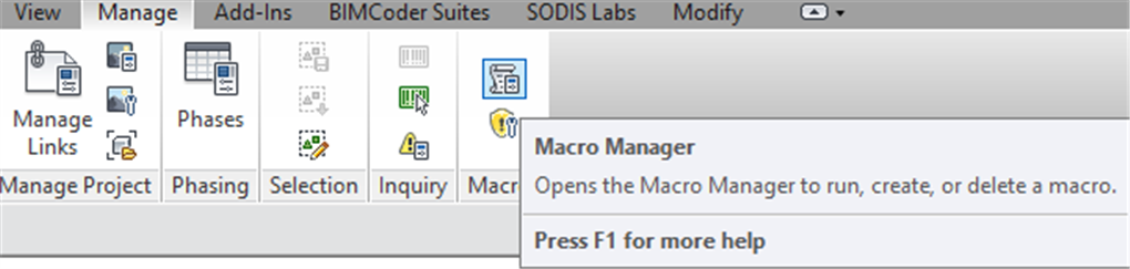
Select Application Tab
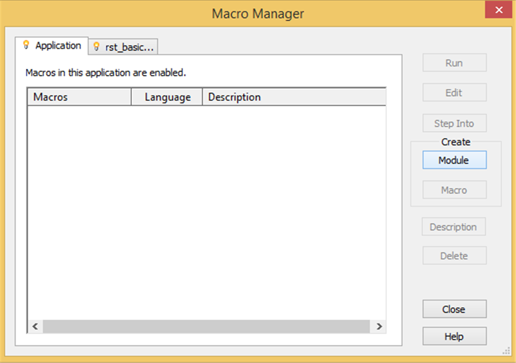
Create C# Module called "KCTCL" (all in capital letters)
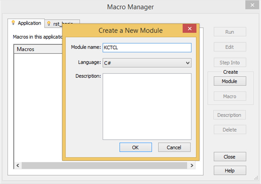
Default codes provided
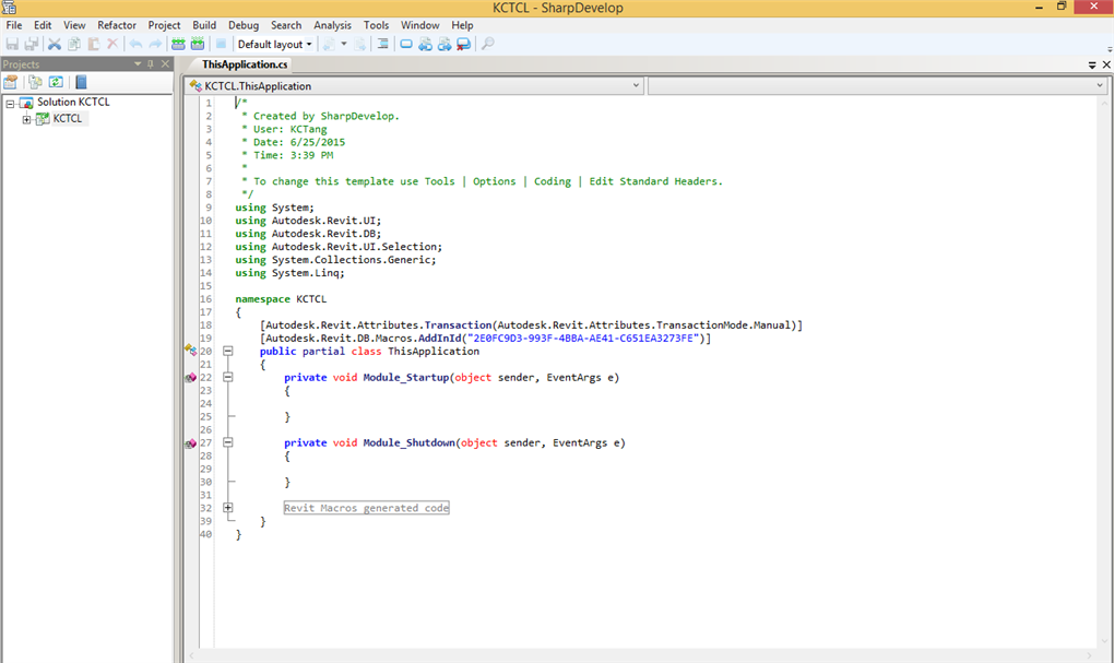
Copy and paste the Codes above
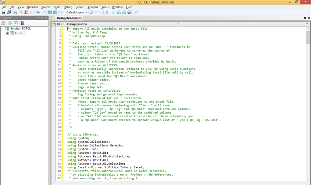
Add Reference
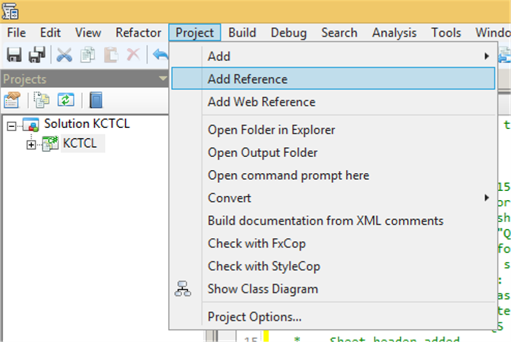
Select Microsoft.Office.Interop.Excel
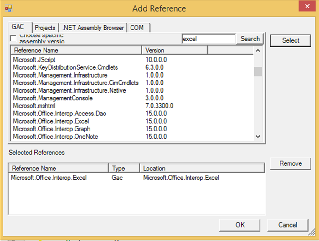
Build Solution
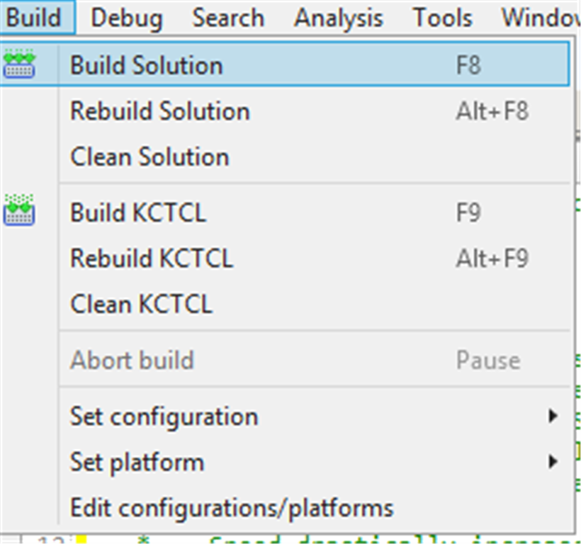
Run
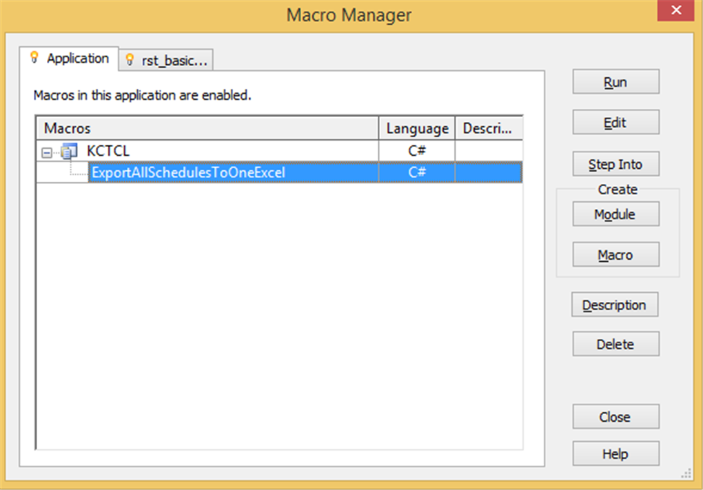
Use pyRevit
Use pyRevit KCTangNote
2/12/2025: Revised to use shared server folder to store site-packages. PyRevit versions updated.
26/3/2025: Updated "Install pyRevit".
21/2/2025: Created.
Intro
pyRevit is an application helping use of Python to develop programming scripts to manage Revit.
The default language used by Revit is C#.
Revit also comes with Dynamo, a graphical programming tool which also uses Python scripts to supplement.
Install Python
(Revised, 2/12/2025)
pyRevit at the time of this writing comes with CPython (3123) and IronPython 2 (2712), which will be used when executing Python scripts through pyRevit.
It would not be necessary to install Python separately to execute scripts through pyRevit, except when additional external Python packages are to be used to extend the functions of pyRevit.
Some external packages are not compatible with IronPython, therefore, CPython has been chosen by our company.
CPython installed separately can also be used on its own when not using pyRevit.
Go to our usual installation source folder.
Click this filename under that file to install Cpython:
- python-3.13.2-amd64.exe
Click to use admin privileges and add python.exe to PATH, then click Install Now to install using the default settings:
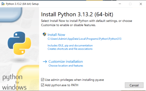
If required, click the same file to choose to modify or remove this Python.
Alternatively, go to Python's official website https://www.python.org/downloads/ to download Python Install Manager or the standalone installer to install Python.
Install external packages
(Added, 2/12/2025)
The following has already been done, but is described here for first time setting up.
Use the file explorer to create this directory: Z:\Data\PythonApps\site-packages
Open Command Prompt window:

The prompt will be: C:\Users\<your username> instead of Admin.
Enter the following lines but after ">" to install additional packages on the server for shared use:
> py -m pip install --target "Z:\Data\PythonApps\site-packages" clr
> py -m pip install --target "Z:\Data\PythonApps\site-packages" openpyxl
It may prompt you to update pip. Enter the following:
> py -m pip install --upgrade pipclr is used to add additional library when running scripts.
openpyxl is used to write and read Excel files without the need to have Excel installed.
The additional packages are stored under:
- Z:\Data\PythonApps\site-packages
The python scripts should contain the following codes to point to this folder before importing the packages in the folder to the scripts for use.
import sys
sys.path.append(r"Z:\Data\PythonApps\site-packages")
If it is desired to install the additional packages on own computer, enter the following lines but after ">":
> py -m pip install clr
> py -m pip install openpyxl
Assuming that Python313 is installed, the additional packages are stored under:
- C:\Users\Admin\AppData\Local\Programs\Python\Python313\Lib\site-packages
The python scripts should contain the following codes to point to this folder before importing the packages in the folder to the scripts for use.
import os
username = os.getlogin()
import sys
sys.path.append("C:\\Users\\" + username + "\\AppData\\Local\\Programs\\Python\\Python313\\Lib\\site-packages")
(or)
sys.path.append(r"C:\Users\" + username + "\AppData\Local\Programs\Python\Python313\Lib\site-packages")
Install pyRevit
Download pyRevit from: https://github.com/pyrevitlabs/pyRevit/releases.
Use the second one. The first one is for the current user only.
📦 pyRevit 5.3.1.25308 Installer
📦 pyRevit 5.3.1.25308 Installer - Admin / All Users / %PROGRAMDATA%
(Versions updated, 2/12/2025)
Click the downloaded file install. The following image shows an old version.
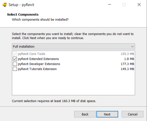
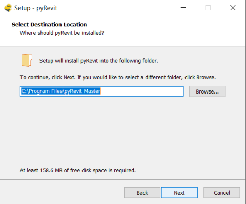
Open Revit. Use Revit 2024 for now.
Click Always Load to confirm loading this new add-in, when prompted after opening Revit after installing pyRevit for the first time.
A menu item for pyRevit should appear.
Click it:

If pyRevit does not appear, check https://pyrevitlabs.notion.site/Install-pyRevit-98ca4359920a42c3af5c12a7c99a196d for solutions.
Click pyRevit on the left:
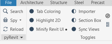
Click Settings on the right:
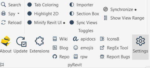
Click add folder to browse to add the file: Z:\Data\PythonApps\PyRevitExtensions, which contains the scripts written by us:
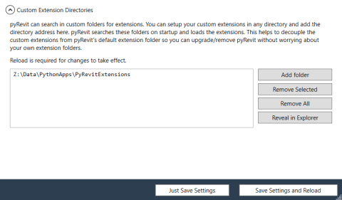
Click Reload to effect the changes:
Reload is required whenever the settings or the scripts have been changed.
Close and re-open Revit if Reload is not effective.
The MyTools menu item will appear next to pyRevit.
Click MyTools to show the following items, clicking which can run the scripts:
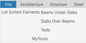
Before running List Sorted Elements, copy the first file without date to the relevant Revit model job folder:
Those with dates are old versions.
The file is a template to define the elements and parameters to output to Excel file format:
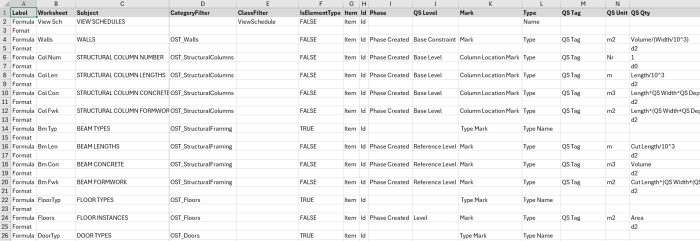
Clicking List Sorted Elements can produce an Excel file with the first worksheet showing the following:
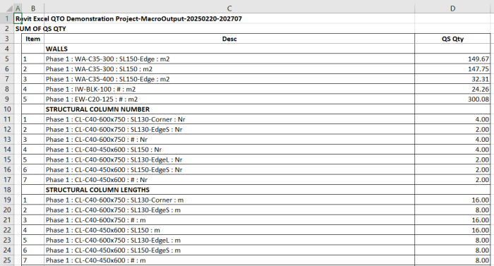
These items can be copied to our normal Excel dimension sheets as secondary quantities for further adjustments to give quantities for Bills of Quantities or Estimates.
There are also other more detailed worksheets generated according to the template settings.
These worksheets can replace Revit's view schedules. However, view schedule entries can be changed on-screen while seeing the model change accordingly.
Linking the Excel files to Revit model in real time is still to be done.
Install Visual Studio Code
Visual Studio Code can be used to write Python scripts.
There are other editors available such as Visual Studio (https://visualstudio.microsoft.com/), pyCharm (https://www.jetbrains.com/pycharm/) and many others which are called Integrated Development Environments or code editors.
Download Visual Studio Code for Windows from here (https://code.visualstudio.com/).
Install it:
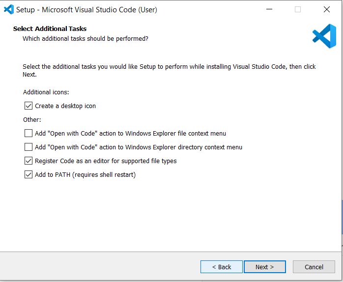
Open it after installation to show:
Select File > Preferences > Themes > Color Theme to list and select the color theme:
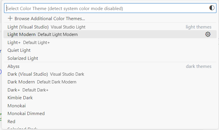
Alternatively, select View > Command Pallet, and enter Color Theme to display the same list to select.
Select the 4-square icon on the left vertical menu, enter pyrevit to show pyRevit with VSCode, and click Install:
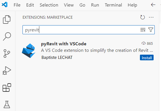
The installation will automatically install:
- Python - Python extension for Visual Studio Code
- Pylance - a fast, feature-rich language support for Python
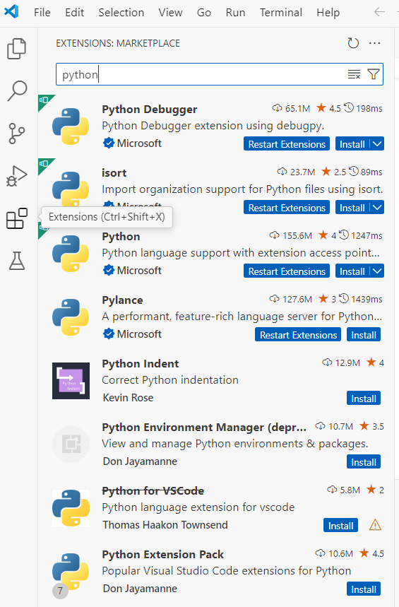
Two pop-up messages will appear:
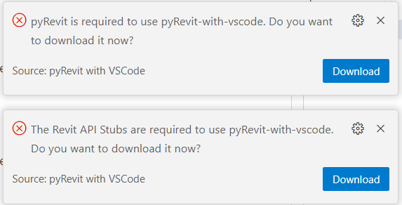
Since pyRevit has already been installed. Do not need to download it.
Click to download Revit API Stubs, which help to display the code syntax when writing codes.
The following folders will be added:
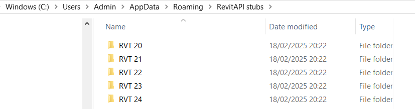
Select View > Command Pallet, and enter inter to filter the list to choose Select Interpreter to choose the previously installed CPython:
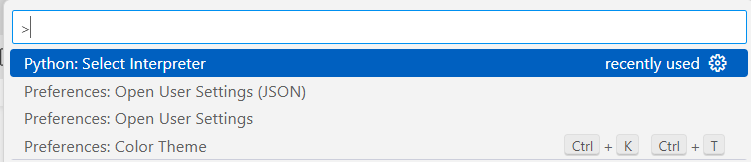
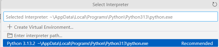
Enter user to filter the list to choose Open User Settings (JSON) as shown above.
Copy and paste the following codes to the Settings:
{
   "workbench.colorTheme": "Default Light+",
   "security.workspace.trust.untrustedFiles": "open",
   "workbench.iconTheme": "vs-minimal",
   "python.analysis.extraPaths": [
       "C:\\Users\\<username>\\AppData\\Roaming\\RevitAPI stubs\\RVT 24",
       "C:\\Program Files\\pyRevit-Master\\pyrevitlib",
       "Z:\\Data\\PythonApps\\PyRevitExtensions\\MyExtension.extension",
   ],
   "python.autoComplete.extraPaths": [
       "C:\\Users\\<username>\\AppData\\Roaming\\RevitAPI stubs\\RVT 24",
       "C:\\Program Files\\pyRevit-Master\\pyrevitlib",
       "Z:\\Data\\PythonApps\\PyRevitExtensions\\MyExtension.extension",
   ],
}
Change <username> to your username on the computer.
The first line of the extraPaths refers to the location of RevitAPI stubs.
The second line refers to the location of pyrevitlib.
The third line refers to the location of the scripts supporting the menu items under Revit's MyTools.
Select File > Open Folder, and browse to select the folder containing the scripts:
- Z:\Data\PythonApps
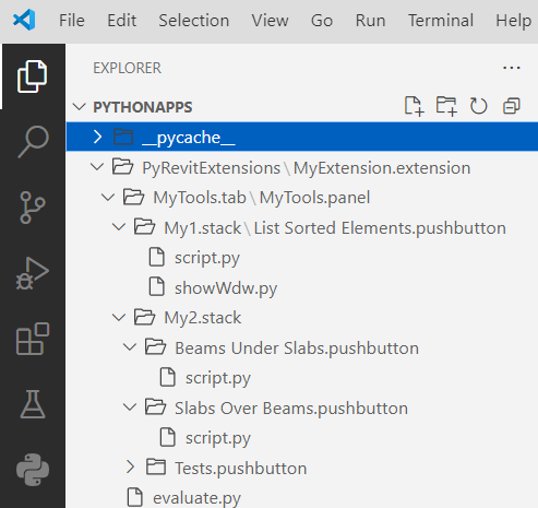
Select the scripts to edit.
Read Standards
Read Standards KCTangStandards (copyrights rest with respective authors and publishers)
UK Standards
- UK HM Government - Industry Strategy - Government and Industry in Partnership - Building Information Modelling 2012.pdf
- UK CIC Building Information Model Protocol first edition 2013.pdf
- CIC Outline Scope of Services for the Role of Information Management first edition 2013.pdf
- CIC Best Practice Guide for Professional Indemnity Insurance when using Building Information Models first edition 2013.pdf
Singapore Standards
Read papers
Read papers KCTangPaper presented at the BIM Seminar Kuala Lumpur 2015 – 5D BIM for the Construction Industry organized by RISM on 22/1/2015
- Minimalist Modelling and Coding of Revit for Quantities.pdf (this is in fact an updated version of the paper presented on 20/2/2014)
- Measure-20150127a.xlsx (BQ, Secondary and Primary Worksheets mentioned in the paper, but slightly updated on 27/1/2015)
- See the macro to export schedules to Excel, and the exported Excel file mentioned in the paper, but updated
Paper presented at the International Workshop for QS BIM Education & Training Content Development organized by RISM on 20/2/2014
Evaluate apps
Evaluate apps KCTangScheduling Apps
Schedule Importer / Exporter by NPO Sodis (Free) - evaluated on 16/1/2014
- Can only export schedules already created in Revit to Excel.
- Cannot define its own schedule.
- Can select schedules in view.
- Can only select and export one schedule at a time.
- Cannot export more than one schedule to one Excel file.
- Cannot partially select and re-order the elements already in the schedule.
- An extra column added for ElementGUID.
Schedule Sync by BIMCODER (Free) - evaluated on 16/1/2014
- Can only export schedules already created in Revit to Excel.
- Cannot define its own schedule.
- Can select schedules not in view.
- Can only select and export one schedule at a time.
- Cannot export more than one schedule to one Excel file.
- Can partially select and re-order the elements already in the schedule.